Method and system for detecting electronic component failures

a technology of electronic components and failure detection, applied in the direction of electric connection testing, measurement devices, instruments, etc., can solve the problems of supporting elements being subject to further use, and achieve the effects of good mechanical connection, easy picking-off of electrical properties, and good connection properties

Inactive Publication Date: 2007-05-01
NOKIA CORP
View PDF3 Cites 9 Cited by
  • Summary
  • Abstract
  • Description
  • Claims
  • Application Information

AI Technical Summary

Benefits of technology

[0026]To provide good information about the mechanical status of the connection between the integrated circuit and the circuit board, it is proposed that said support elements are arranged between said circuit board and said integrated circuit package. This ensures on the one hand good mechanical connection between the IC and PWB and on the other hand, allows easy access to mechanical conditions of the connection.
[0027]Good connecting properties and also easy picking-off of electrical properties of the support elements are possible in case said support elements are solder pads. These provide good mechanical properties with respect to coupling the IC on the PWB. This also provides good electrical properties being used when picking-off the physical values for determination of the mechanical condition of the connection.
[0028]To provide a close relationship between the mechanical condition of the support elements and the electrical condition of the coupling elements, it is preferred to arrange said support elements adjacent to said coupling elements. It has been detected that arranging said support elements semicircular along said coupling elements provides good results. This is because this arrangement may detect any mechanical stress on the support elements (i.e. shear forces, torque, tensile force, pulling force, . . . ). According to another embodiment, also providing good results in terms of detecting mechanical stress, it is proposed that said support elements are arranged along edges and / or at corners of said integrated circuit package.
[0029]To provide high integration of integrated circuits and to provide good failure analysis, it is proposed that said integrated circuit package is a chip scale package or a chips size package.

Problems solved by technology

As each integrated circuit package, such as a CSP, has to be mounted by support elements onto a wiring board, as a PWB, the support elements may be subject to a further use, such as failure analysis.

Method used


Image

  • Method and system for detecting electronic component failures
  • Method and system for detecting electronic component failures
  • Method and system for detecting electronic component failures

Examples


Embodiment Construction

[0045]Table 1 identifies the reference numerals used in the specification and drawings.

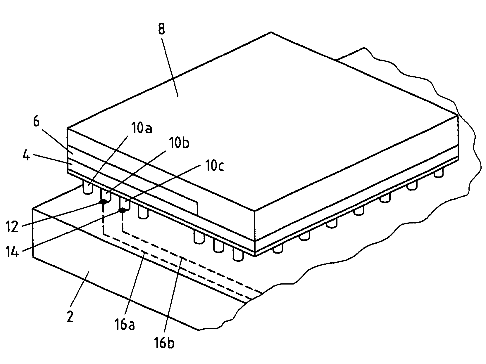
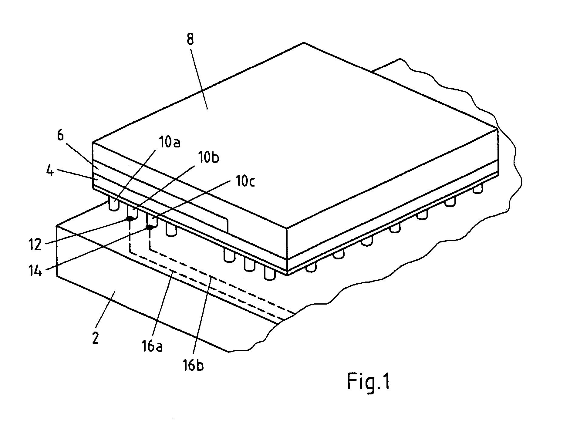
[0046]FIG. 1 depicts a sectional view of an inventive assembly. An integrated circuit package comprising a substrate 4, a die 6 and, a mold 8 is mounted on a printed wiring board 2.

[0047]The integrated circuit package is mechanically coupled to the printed wiring board 2 by support elements 10, such as solder balls. Electrically, the integrated circuit package is connected to the printed wiring board 2 by a ball grid array (not depicted).

[0048]To enable determining the status of the mechanical connection between the printed wiring board 2 and the integrated circuit package, it is proposed to pick-off electrical values from the support elements 10.

[0049]As depicted in FIG. 1, support element 10b has a tap 12, which is connected to connection wire 16a. Support element 10c has a tap 14, being electrically coupled to wire 16b. Support element 10b is electrically connected to support element 10c on the...


PUM


Abstract

The invention relates to a method for analysing connection conditions between an integrated circuit package and a circuit board, wherein said integrated circuit package is electrically coupled to said circuit board by coupling elements, and therein said integrated circuit package is mechanically connected with said circuit board by support elements. To allow easy failure analysis, it is proposed that physical values are picked-off from said support elements, and said physical values are evaluated to determine the condition of said connection between said integrated circuit package and said circuit board.

Description

FIELD OF THE INVENTION[0001]The invention relates to a method for analysing connection conditions between an integrated circuit package and a circuit board, wherein said integrated circuit package is electrically coupled to said circuit board by coupling elements, and wherein said integrated circuit package is mechanically connected with said circuit board by support elements.[0002]The invention also relates to a system for analysing connection conditions between an integrated circuit package and a circuit board, comprising coupling elements coupling said integrated circuit package electrically to said circuit board, and support elements connecting said integrated circuit package mechanically with said circuit board.[0003]Further, the invention relates to a consumer electronic device, in particular a mobile phone, comprising such a system.[0004]The invention further relates to a computer program and a computer program product for analysing connection conditions between an integrated...

Claims


Application Information

Patent Timeline
Patent Type & Authority Patents(United States)
IPC IPC(8): G01R31/02G01R31/04
CPCG01R31/046G01R31/043G01R31/68G01R31/70
Inventor VENTOMAKI, HANNU
Owner NOKIA CORP
Why Eureka
Try Eureka