Monolithic waveguide arrays

a monolithic waveguide and array technology, applied in the field of dielectric waveguides, can solve the problems of preventing the bundle from being bundled, the fibers within the bundle cannot be stacked regularly, and the flexibility of the fiber-bundle endoscope structure remains significant,

Inactive Publication Date: 2007-05-01
UNIV OF COLORADO THE REGENTS OF
View PDF6 Cites 24 Cited by
  • Summary
  • Abstract
  • Description
  • Claims
  • Application Information

AI Technical Summary

Benefits of technology

[0009]There are a variety of different ways in which the optical intensity pattern may be generated in different embodiments. In one embodiment, the photoreactive material is illuminated with a first set of coherent waves focused onto a portion of a plane passing through the photoreactive material. The portion of the plane is also illuminated with a second set of coherent waves that are incoherent with the first set of waves to generate an interference pattern in the portion of the plane. In some instances, the portion of the plane may further be illuminated with a third set of mutually coherent waves, thereby refining control over the exposure and thus the index distribution. Each set of waves is coherent only with itself, thus forming interference patterns only with itself, permitting the addition, either simultaneously or in a later exposure of additional sets of waves to expose the material with additional patterned exposure.

Problems solved by technology

But, even so, such fiber-bundle endoscope structures still suffer from significant limitations in flexibility.
In addition, the fibers within the bundles cannot typically be stacked regularly, prohibiting the bundles from being identically matched to a grid of pixels on a camera or display chip.
Fiber endoscopes thus provide relatively low performance characteristics, are stiff and heavy, and are costly.
But even in such medical applications, recent studies have identified risks of transferring infections among patients as endoscopes are reused because of the formation of antibiotic-resistant bacterial biofilms.

Method used


Image

  • Monolithic waveguide arrays
  • Monolithic waveguide arrays
  • Monolithic waveguide arrays

Examples


Embodiment Construction

1. Overview

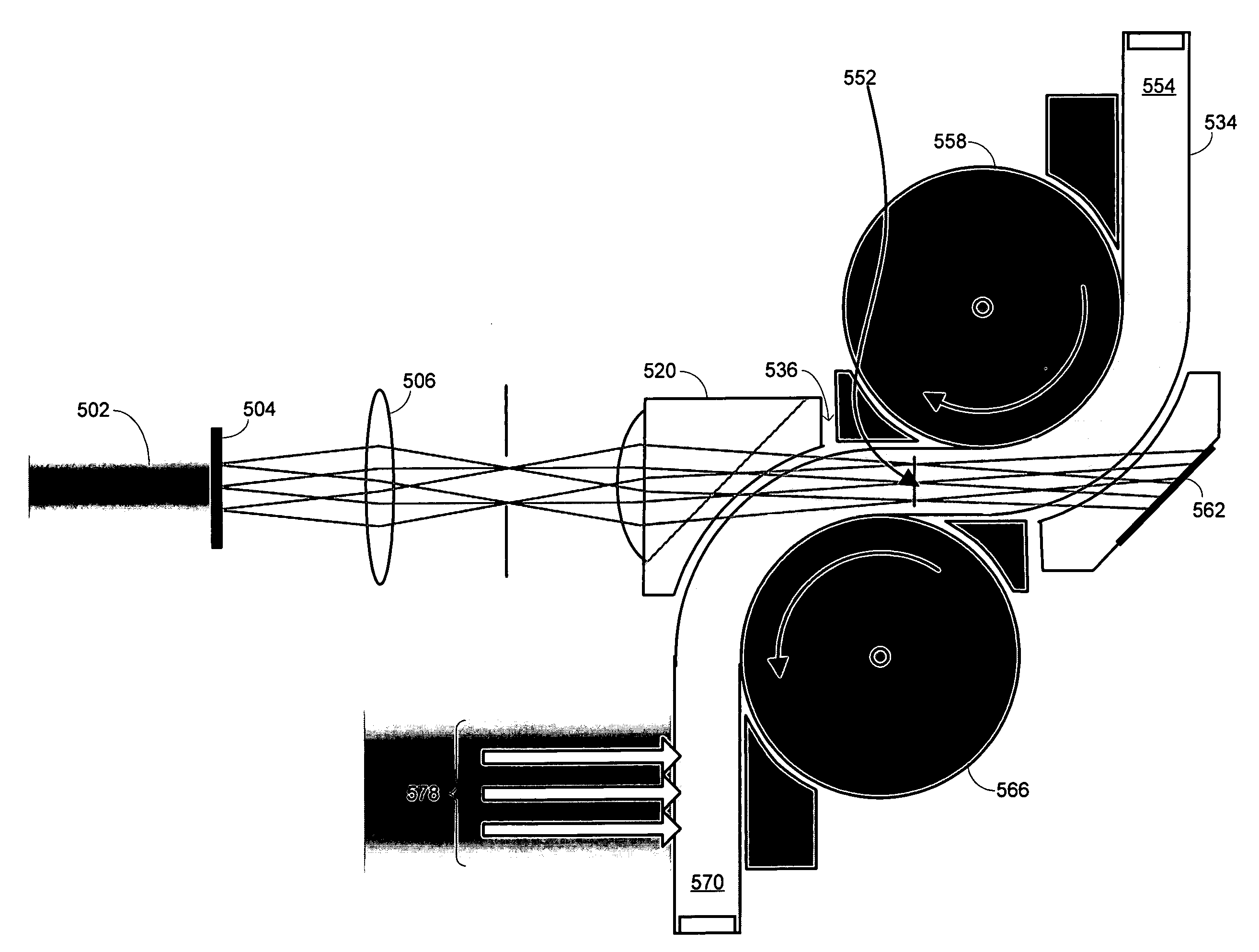
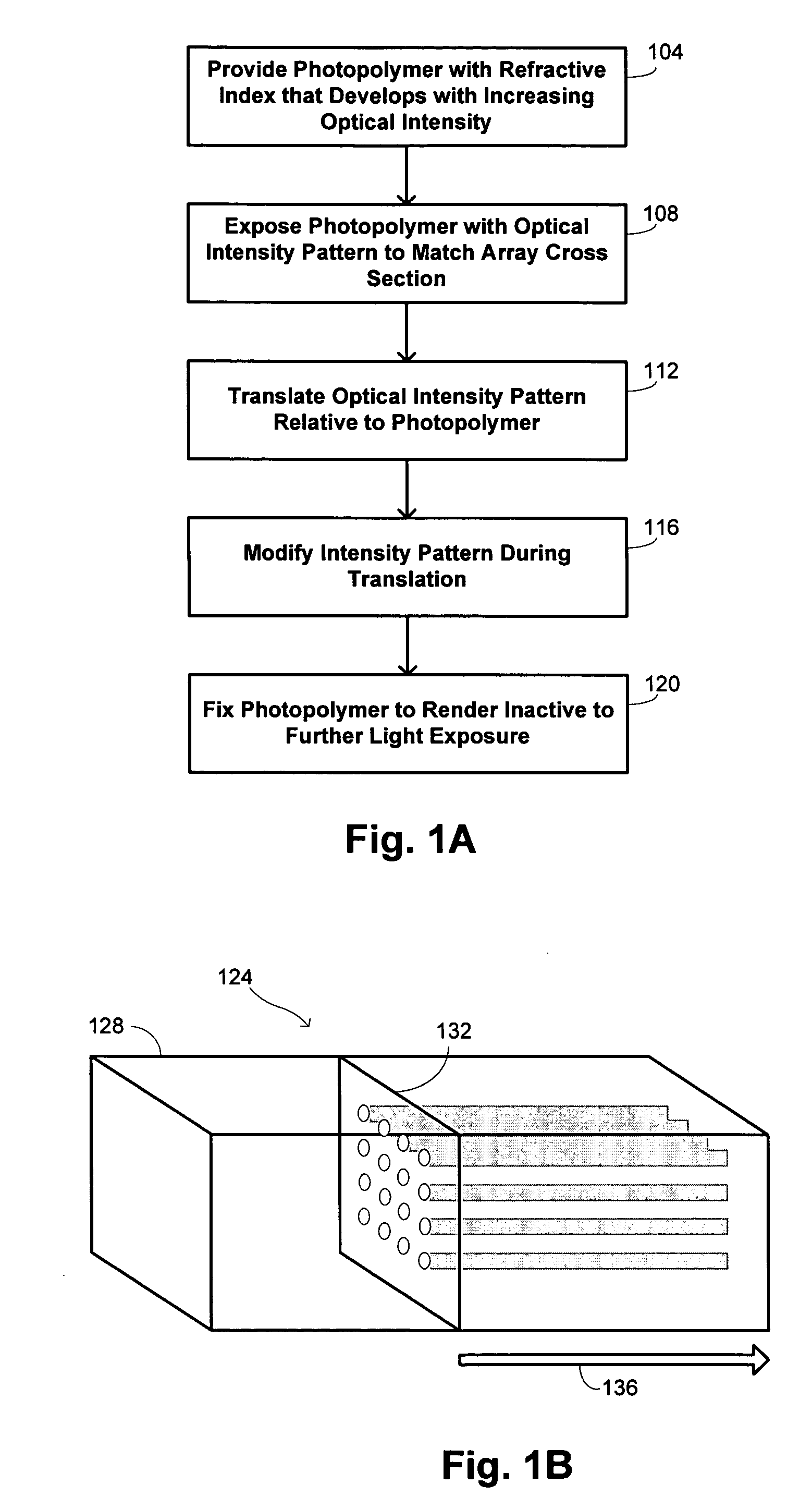
[0030]Embodiments of the invention provide monolithic waveguide arrays that may be used in a wide array of applications, including endoscopic and other applications, as well as methods for fabricating such monolithic waveguide arrays. The monolithic waveguide arrays may comprise a plurality of waveguides formed from a photoreactive material that changes its refractive index in response to exposure to light of an appropriate wavelength. In certain embodiments, the photoreactive material comprises a photopolymeric material. Specific details of the process are sometimes described below with specific reference to such photopolymeric materials without intended to depart from the more general aspects of the invention.

[0031]The photoreactive properties of the material are exploited by creating an optical intensity pattern corresponding to the desired array for the waveguides. This optical intensity pattern is then translated relative to the photoreactive material to cause the de...


PUM

PropertyMeasurementUnit
wavelengthaaaaaaaaaa
lengthaaaaaaaaaa

Abstract

A waveguide array is fabricated by providing a photoreactive material and generating an optical intensity pattern corresponding to a geometry of the waveguide array. A relative translation of the photoreactive material is effected through the optical intensity pattern. Thereafter, the photoreactive material is rendered substantially unreactive to light at at least a wavelength of the optical intensity pattern.

Description

CROSS-REFERENCES TO RELATED APPLICATIONS[0001]This application is a nonprovisional of, and claims the benefit of the filing date of U.S. Prov. Pat. Appl. No. 60 / 654,711, entitled “POLYMER WAVEGUIDE ARRAYS,” filed Feb. 19, 2005 by Robert R. McLeod and Eric D. Moore, the entire disclosure of which is incorporated herein by reference for all purposes.BACKGROUND OF THE INVENTION[0002]This application relates generally to dielectric waveguides. More specifically, this application relates to the formation of monolithic waveguide arrays.[0003]Endoscopes are devices that are used to deliver images from constricted locations and / or through small openings. While endoscopes have the potential to find a wide range of application, they are currently used primarily for diagnostic medical applications. In such applications, an endoscope is inserted into a portion of a patient's body and used to collect images of the portion that may be studied by qualified technicians and / or physicians to aid in t...

Claims


Application Information

Patent Timeline
Patent Type & Authority Patents(United States)
IPC IPC(8): G02B6/00
CPCG02B6/13G02B6/138
Inventor MCLEOD, ROBERT R.MOORE, ERIC D.
Owner UNIV OF COLORADO THE REGENTS OF
Why Eureka
Try Eureka