Antenna unit and receiving circuit

a technology of receiving circuit and antenna unit, which is applied in the direction of amplification control details, transmission, gain control, etc., can solve the problems of large cable attenuation, large distortion, small gain of low-directivity receiving antenna, etc., and achieve wide dynamic range

Inactive Publication Date: 2007-05-01
SONY CORP
View PDF13 Cites 9 Cited by
  • Summary
  • Abstract
  • Description
  • Claims
  • Application Information

AI Technical Summary

Problems solved by technology

However, the gain of a low-directivity receiving antenna is small.
When the signals A3 and B3 are received near the transmitting antenna, the reception levels rise considerably, so that the high-frequency amplifier becomes saturated, causing large distortion.
As mentioned above, however, the DARS broadcasts use the 2.3 GHz band, so attenuation caused by the cable is large.
Accordingly, the variable gain amplifier cannot be used as a high-frequency amplifier in which low noise is required.

Method used


Image

  • Antenna unit and receiving circuit
  • Antenna unit and receiving circuit
  • Antenna unit and receiving circuit

Examples


Embodiment Construction

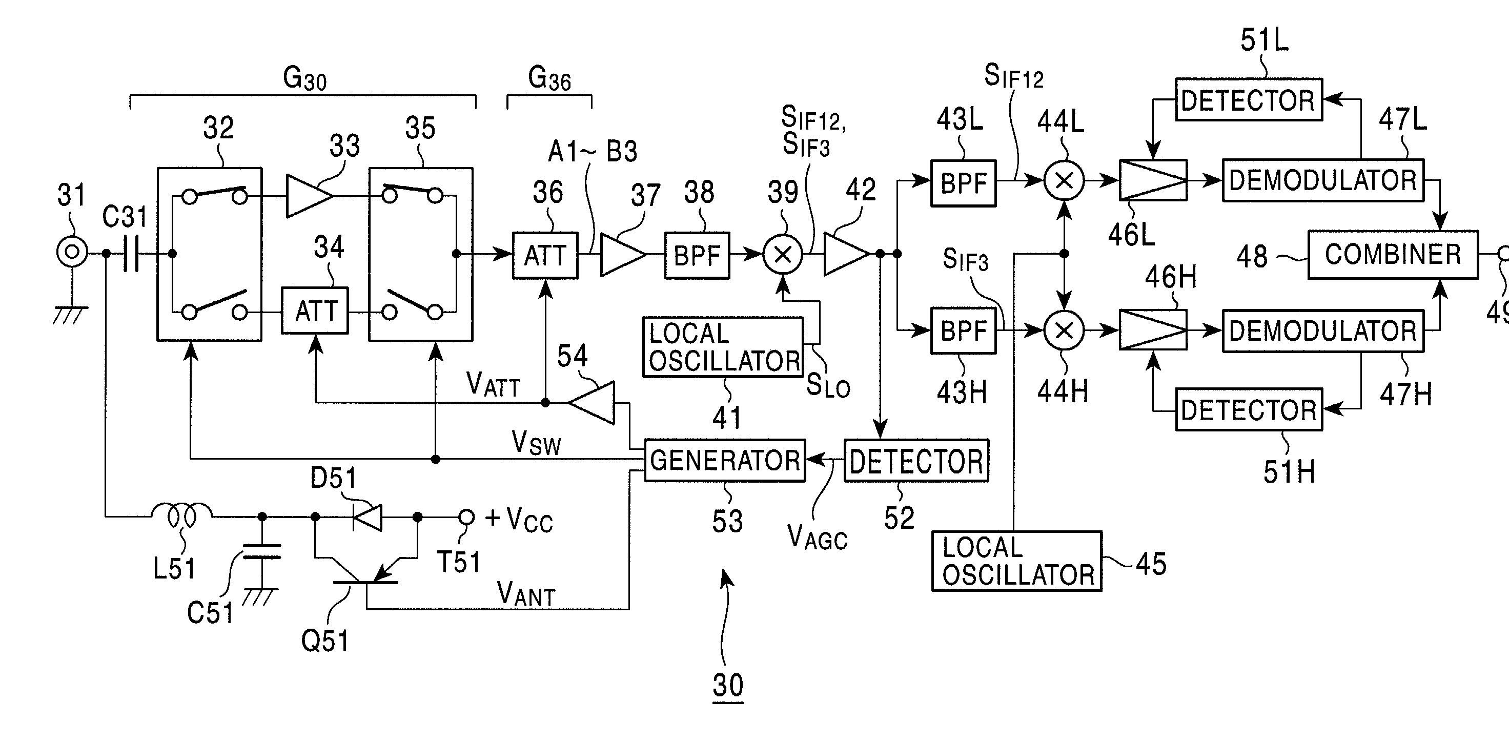
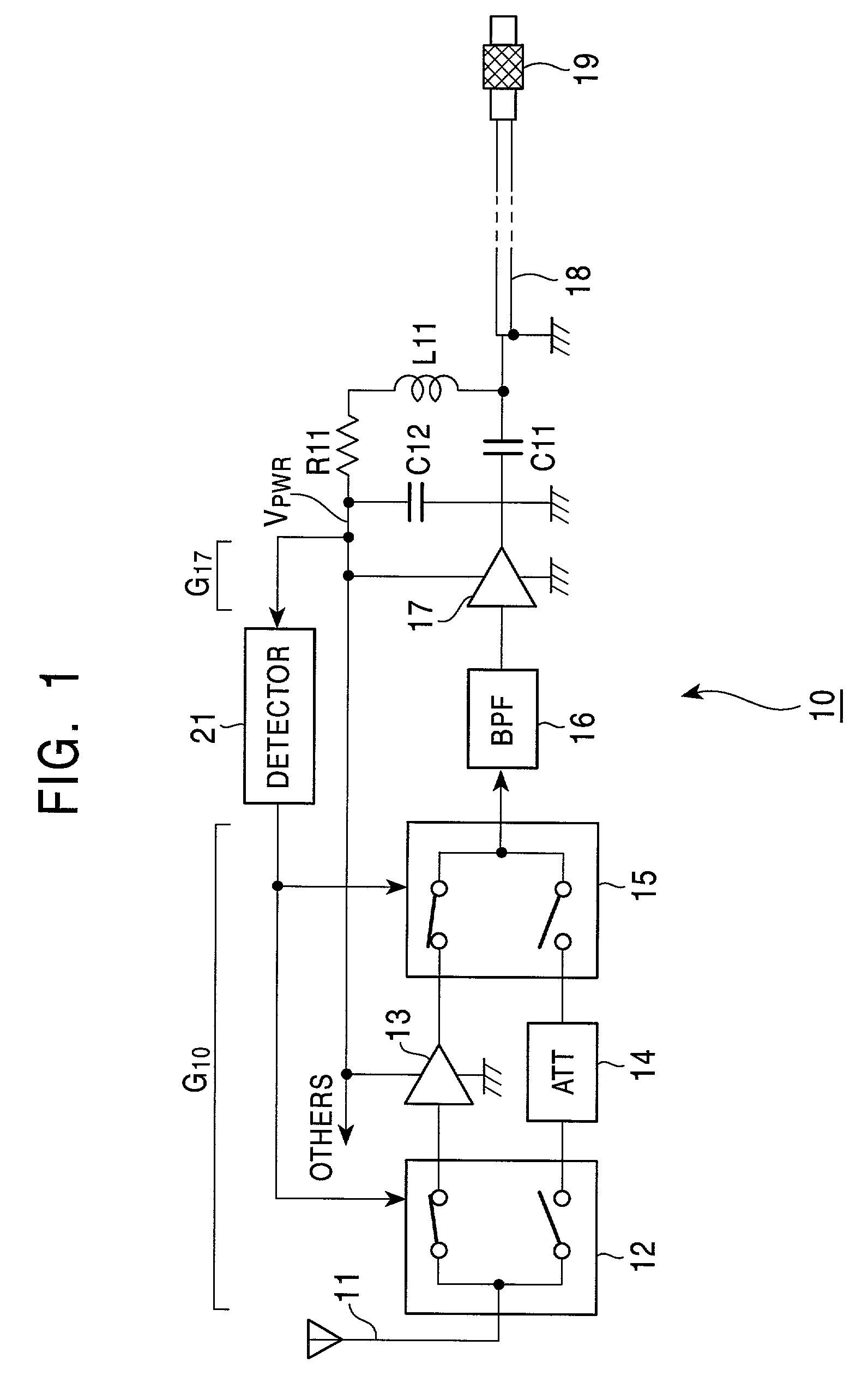
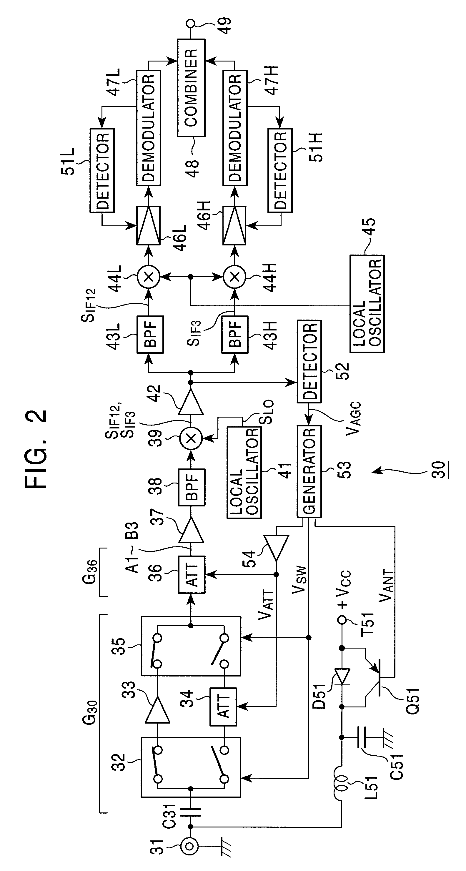
[0033]FIGS. 1 and 2 show an example of a case where the present invention is applied to an antenna unit and a receiver for receiving DARS signals. Reference numeral 10 denotes an antenna unit and reference numeral 30 indicates a receiver.

[0034]In the antenna unit 10, a receiving antenna 11 for the DARS signals A1 to B3 is connected to a high-frequency amplifier 13 or an attenuator circuit 14 via a switching circuit 12. In this case, to selectively connect the antenna 11 to one of the high-frequency amplifier 13 and the attenuator circuit 14, the switching circuit 12 has a switching element such as a gallium arsenide FET (field effect transistor), in which the loss or noise is low when turned on, which exhibits excellent isolation when turned off, and which has excellent high-frequency characteristics. The switching circuit 12 is represented as a single-pole double-throw switch in FIG. 1.

[0035]The high-frequency amplifier 13 comprises a low-noise amplifier. A gain G13 thereof is fixe...


PUM


Abstract

An antenna unit includes an antenna, a high-frequency amplifier, an attenuator circuit, an output cable, and a voltage detector circuit. An operating voltage is supplied from a receiver to the high-frequency amplifier through the output cable. The operating voltage changes in accordance with an automatic gain control (AGC) voltage. The voltage detector circuit detects a change in the operating voltage. In response to the voltage detector circuit output, one of the high-frequency amplifier and the attenuator circuit is selectively connected to a signal line between the antenna and the output cable.

Description

BACKGROUND OF THE INVENTION[0001]1. Field of the Invention[0002]The present invention relates to an antenna unit and a receiver.[0003]2. Description of the Related Art[0004]Digital audio broadcasting in the U.S. is called DARS (Digital Audio Radio Service). To realize stable reception in a receiver mounted in a vehicle, DARS uses both satellite waves and terrestrial waves.[0005]That is, DARS uses the 2.3 GHz band. As shown in part B in FIG. 8, two services are transmitted. In this instance, each of the services uses a frequency bandwidth of 12.5 MHz. As shown in part A in FIG. 8, one service comprises two ensembles A and B. Each of the ensembles A and B provides 50 channels of programs (contents). Accordingly, one service provides 100 channels of programs.[0006]The ensemble A is transmitted by signals A1, A2, and A3. The ensemble B is transmitted by signals B1, B2, and B3. That is, the contents of the signals A1, A2, and A3 are identical to each other. The contents of the signals B1...

Claims


Application Information

Patent Timeline
Patent Type & Authority Patents(United States)
IPC IPC(8): H04B1/06H04B1/18H01Q23/00H03G1/00H03G1/02H03G3/20H03G3/30H04B1/16H04B1/26
CPCH03G1/0088H03G3/3036H03F2203/7239H04B1/26
Inventor OKANOBU, TAIWA
Owner SONY CORP
Why Eureka
Try Eureka