
Solid fuel burner, solid fuel burner combustion method, combustion apparatus and combustion apparatus operation method

a solid fuel burner and burner technology, applied in the direction of combustion regulation, combustion types, lighting and heating apparatuses, etc., can solve the problems of restricted oxidation reaction of this fuel, difficult to handle, and spontaneous ignition, so as to avoid slugging, reduce combustibility, and stable combustion

Active Publication Date: 2007-05-08
MITSUBISHI HITACHIPOWER SYST LTD
View PDF5 Cites 7 Cited by
  • Summary
  • Abstract
  • Description
  • Claims
  • Application Information

AI Technical Summary

Benefits of technology

The design ensures stable combustion across varying loads by enhancing fuel-air mixing, reducing unburnt fuel and NOx emissions, and preventing slugging, while maintaining efficient operation and minimizing production costs.

Problems solved by technology

Since fuel such as wood, peat and coal having a low coalification rank, represented by brown coal and lignite, contains much volatile matter, in the atmosphere of air, such a fuel tends to undergo spontaneous ignition in the process of storage, pulverization and feed, and is not easy to handle, as compared to the bituminous coal.
However, when the fuel carried by the carrier gas is jetted from the solid fuel burner, the oxidation reaction of this fuel is restricted by the oxygen concentration around the fuel, and the combustion speed is low as compared to the cases where the fuel is carried by air.
This will lead to increase in the amount of the unburnt fuel at the outlet of the combustion apparatus, i.e. the furnace
Further, flame temperature is low since combustion is slow.
This makes it difficult to utilize the reduction reaction of the nitrogen oxides (NOx) into nitrogen, which becomes active in a reducing atmosphere of high temperature (about 1000° C. or higher).
If the air from the additional air nozzle is jetted in the form of fuel jet, viz., in parallel to the fuel and its carrier gas as in the case of the aforementioned prior art examples, mixing between the fuel jet and additional air will be slow because there is a small difference in flow velocity between the fuel jet and the air jet from the additional air nozzle.
If the additional air is jetted in parallel to the fuel particle, mixing will be insufficient.
Thus, the distance from the additional air nozzle outlet to the fuel nozzle outlet cannot be increased.

Method used


Image

  • Solid fuel burner, solid fuel burner combustion method, combustion apparatus and combustion apparatus operation method
  • Solid fuel burner, solid fuel burner combustion method, combustion apparatus and combustion apparatus operation method
  • Solid fuel burner, solid fuel burner combustion method, combustion apparatus and combustion apparatus operation method

Examples


embodiment 1

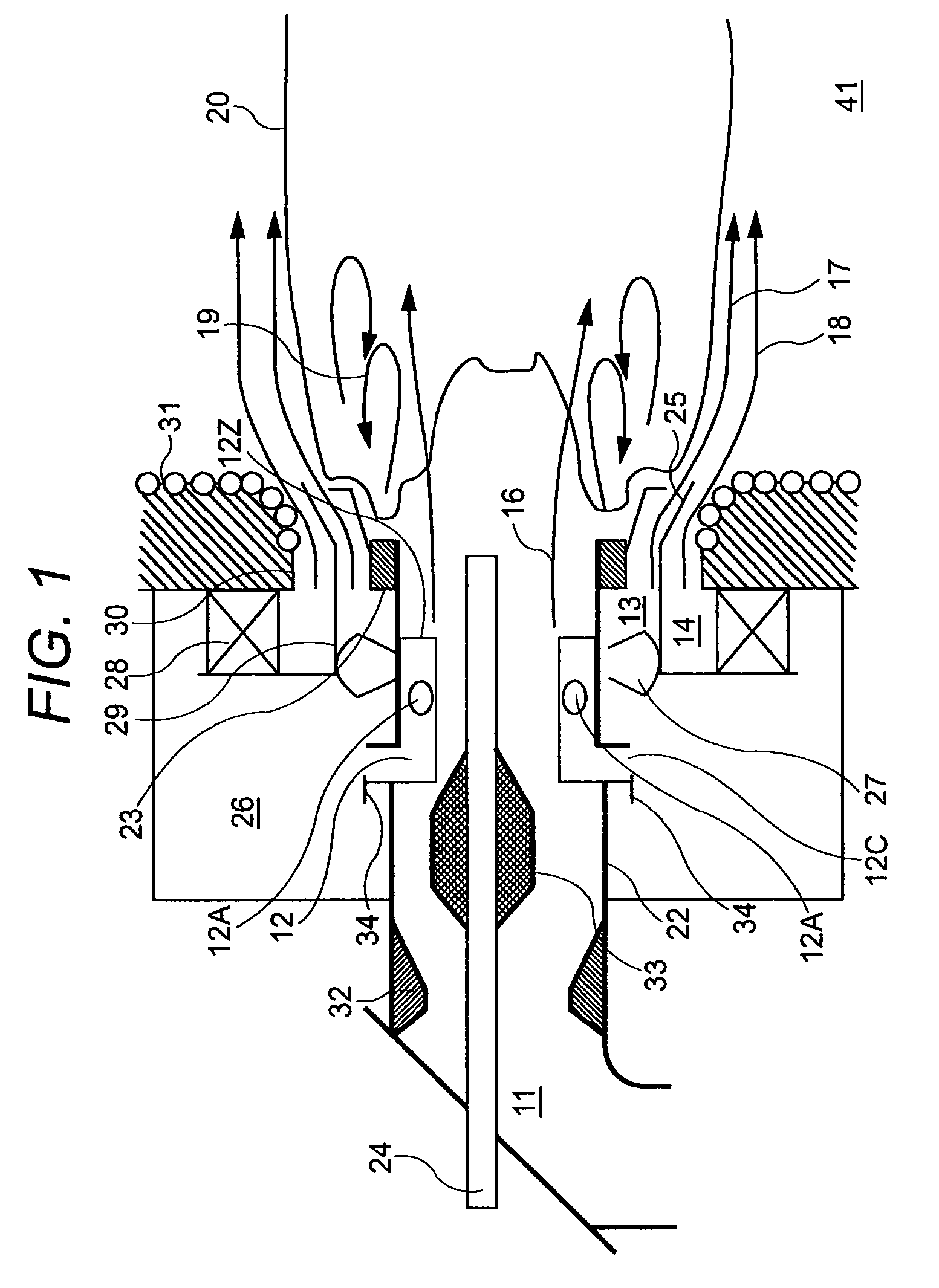
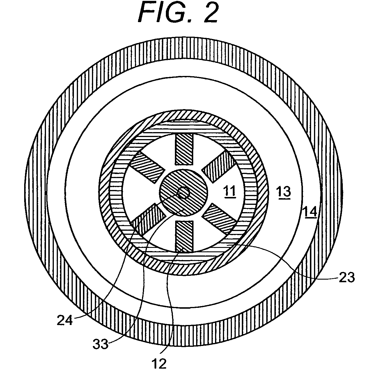
[0086]FIG. 1 is a cross-sectional view representing the configuration of a first embodiment of a solid fuel burner according to the present invention. It shows that, when the solid fuel burner as the first embodiment is used under light load, the flame 20 of the solid fuel burner is formed from the vicinity of a circulating flow 19 downstream of the flame holder or stabilizer 23. FIG. 2 is a diagram showing the schematic configuration of the solid fuel burner as the first embodiment, as viewed from the side of a furnace 41.

[0087]The solid fuel burner of the first embodiment is equipped with an oil gun 24 for combustion improvement arranged at the center. A fuel nozzle 11 for jetting the fuel jet, viz., fuel and its carrier gas 16 is arranged around the oil gun 24 for combustion improvement.

[0088]The oil gun 24 for combustion improvement provided through the center of the fuel nozzle 11 is used for fuel ignition in starting the solid fuel burner.

[0089]A flow path reducing member (ven...

embodiment 2

[0128]FIG. 6 is a diagram showing the schematic configuration of a second embodiment of the solid fuel burner according to the present invention, viewed from the side of the furnace 41.

[0129]In FIG. 6, there is no concentrator 33, and at least some parts of the outside air nozzles such as the secondary air nozzle 13 and tertiary air nozzle 14 are installed so as to sandwich the fuel nozzle 11, as compared to the case shown in FIG. 2. It is also possible to arrange such a configuration that the fuel nozzle 11 or the concentrator 33 is rectangular. Further, it is possible to make such arrangements that the outside air nozzles such as the secondary air nozzle 13 and tertiary air nozzle 14 are integrally formed as one nozzle, or the outside air nozzles are separated into three or more components.

embodiment 3

[0130]FIG. 7 is a sectional view showing the configuration of a third embodiment of the solid fuel burner according to the present invention, wherein the flame of the solid fuel burner is formed close to the circulating flow downstream of the flame holder when the solid fuel burner is used under light load.

[0131]In the third embodiment, an inside air nozzle 38 is provided in the fuel nozzle 11 of the solid fuel burner 42 and is connected with an air box through a pipe. Part of the air supplied to the solid fuel burner is jetted from the inside air nozzle 38.

[0132]When air is mixed through the fuel nozzle 11, the mixing between fuel and air is carried out faster than it is mixed only through the outside air nozzles 13 and 14. Further, when a large quantity of air is jetted from the inside air nozzle 38, the flow velocity of the fuel jet 16 is increased to permit the position of fuel ignition to be separated from the solid fuel burner 42.

[0133]Thus, when a flame is formed away from th...


PUM


Abstract

A solid fuel burner and its combustion method suited for encouraging fuel ignition and avoiding slugging caused by combustion ash, wherein a gas of low oxygen concentration (exhaust combustion gas) is used as a carrier gas of such a low grade solid fuel as brown coal.Means for Solving the SubjectAn additional air nozzle 12 for jetting additional air having a velocity component in the circumferential direction of a fuel nozzle 11 is provided in the fuel nozzle 11, thereby encouraging mixing between the fuel and air in the fuel nozzle 11. Further, the amount of air supplied from the additional air nozzle 12 is adjusted in response to the difference in combustion loads. Under light load, the amount of air supplied from the additional air nozzle 12 is increased so as to increase the oxygen concentration of the circulating flow 19 formed downstream of the outside of the outlet of the fuel nozzle 11, whereby stable combustion is ensured. Under heavy load, by contrast, the amount of air supplied from the additional air nozzle 12 is decreased, and a flame is formed away from the fuel nozzle 11 in such a way that burner structures and furnace wall will be less subjected to radiant heat.

Description

BACKGROUND OF THE INVENTION[0001]1. Technical Field of the Invention[0002]The present invention relates to a solid fuel burner for burning a solid fuel fed by gas flow, particularly to a solid fuel burner, a solid fuel burner combustion method, a combustion apparatus (combustion apparatus) equipped with solid fuel burners and an operation method of the combustion apparatus, suitable for suspended combustion of such fuels as wood, peat and coal, containing much water and volatile matter by pulverizing and feeding them by gas.[0003]2. Description of Prior Art[0004]Since fuel such as wood, peat and coal having a low coalification rank, represented by brown coal and lignite, contains much volatile matter, in the atmosphere of air, such a fuel tends to undergo spontaneous ignition in the process of storage, pulverization and feed, and is not easy to handle, as compared to the bituminous coal. To prevent spontaneous ignition, when such a fuel is pulverized and burnt, the gas mixture of ai...

Claims


Application Information

Patent Timeline
Patent Type & Authority Patents(United States)
IPC IPC(8): F23D1/00F23N5/02F23C99/00F23K3/02F23L1/00
CPCF23D1/00F23D2201/20F23D2201/30
Inventor OKAZAKI, HIROFUMIYAMAMOTO, KENJIKIYAMA, KENJIKURAMASHI, KOUJI
Owner MITSUBISHI HITACHIPOWER SYST LTD
Learn More