Equipment and method for polishing both sides of a rectangular substrate

a technology for rectangular substrates and polishing equipment, applied in the direction of gear teeth, gear teeth, gear teeth, etc., can solve the problems of affecting the consistency of thickness, requiring a large footprint for single-sided polishing equipment, and reducing the thickness of the substrate, so as to achieve the effect of improving the consistency of thickness

Inactive Publication Date: 2007-05-08
OKAMOTO MACHINE TOOL WORKS LTD
View PDF17 Cites 16 Cited by
  • Summary
  • Abstract
  • Description
  • Claims
  • Application Information

AI Technical Summary

Benefits of technology

[0015]Both sides of the rectangular substrate are polished using eccentric rectangular polishing pads that, while oscillating the rectangular substrate laterally, rotate in opposite directions from each other, so the difference in thickness between the four corners and other areas of the polished rectangular substrate becomes smaller. In other words, a rectangular substrate that is improved in consistency of thickness can be obtained. In addition, a pair of eccentric rectangular polishing pads, the centers of rotational axes of which are remotely spaced from each other, rotate in opposite directions from each other, so a thin rectangular substrate will not deviate from the pocket of the carrier while being polished.

Problems solved by technology

However, polishing each side separately requires more polishing-process stages as well as a procedure to turn over the rectangular glass plate halfway through the process, so polishing equipment becomes more bulky than double-sided polishing equipment that can polish both sides of a rectangular glass plate at the same time.
In other words, single-sided polishing equipment requires a big footprint, which is a disadvantage.

Method used


Image

  • Equipment and method for polishing both sides of a rectangular substrate
  • Equipment and method for polishing both sides of a rectangular substrate
  • Equipment and method for polishing both sides of a rectangular substrate

Examples


Embodiment Construction

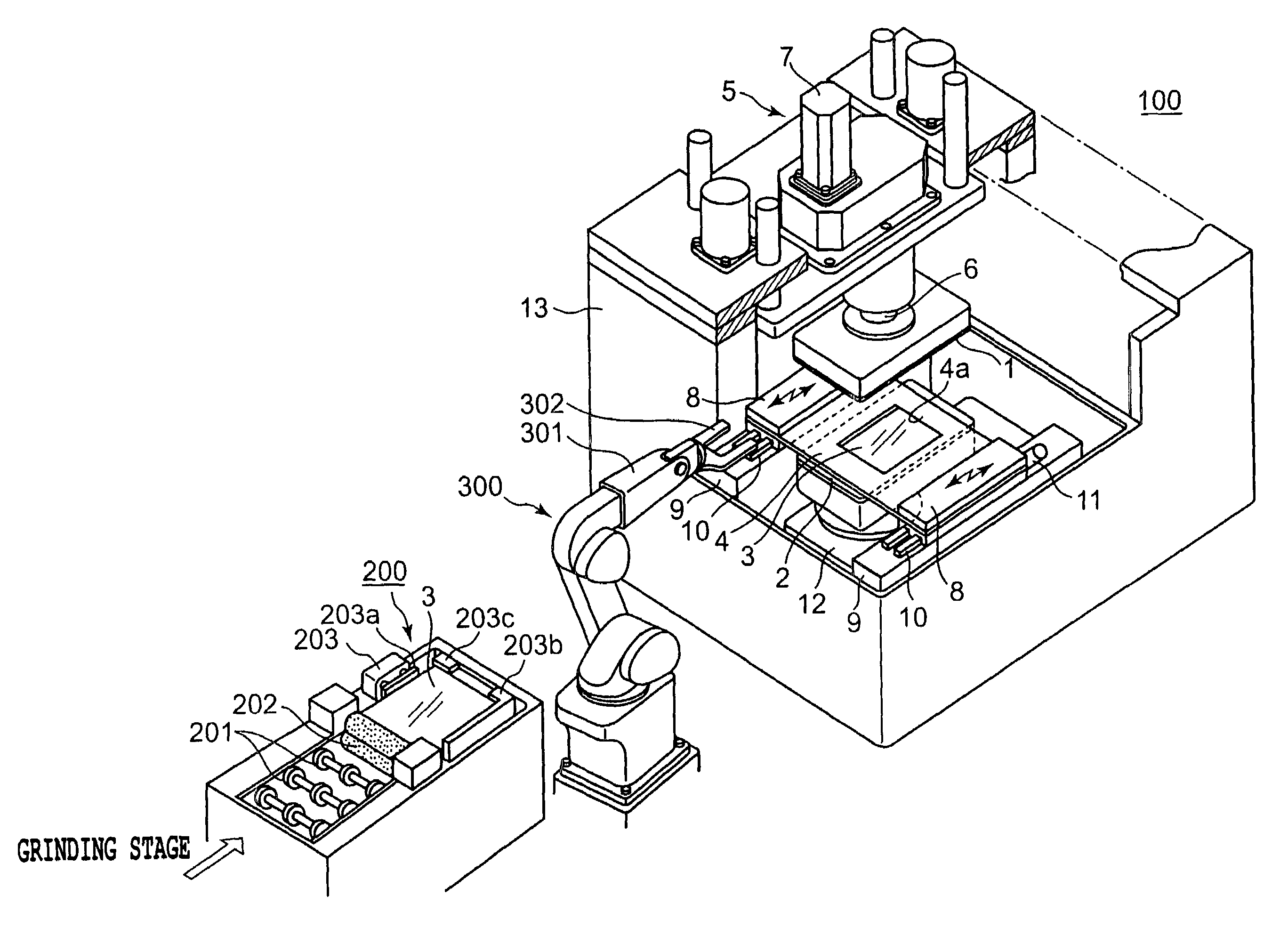
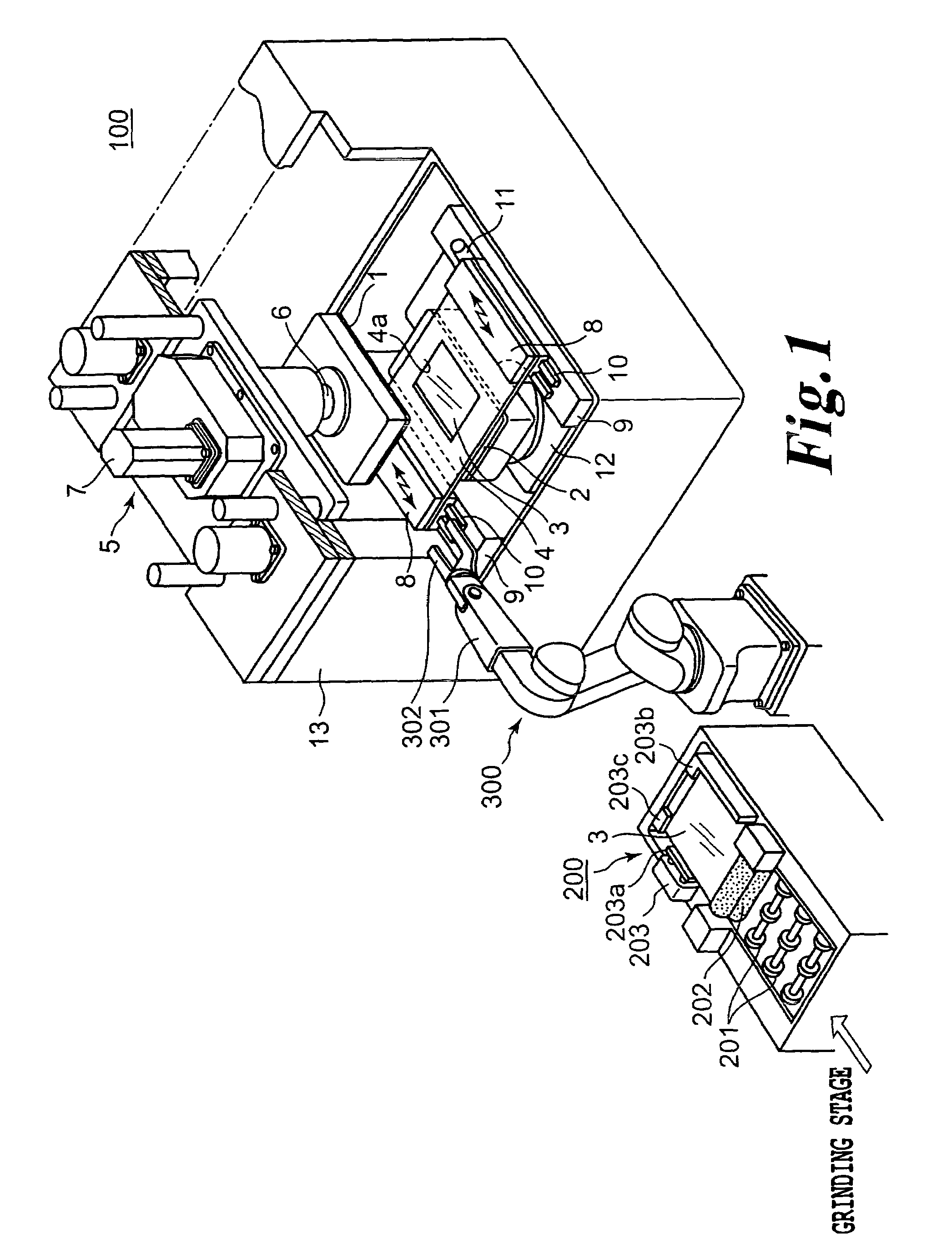
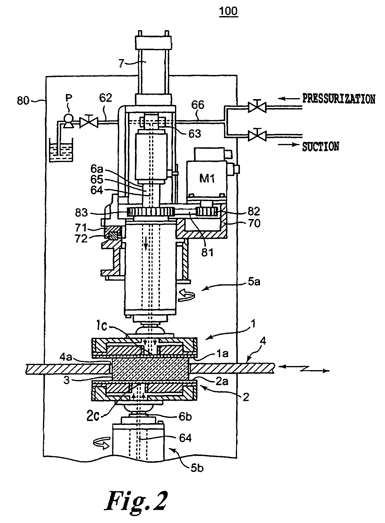
[0022]Referring now to the drawings, wherein like reference numerals designate identical or corresponding parts throughout the several views, in the non-limiting embodiment shown in FIG. 1, 100 is a double-sided polishing equipment for a rectangular substrate, 1 is an upper rectangular polishing pad, 2 is a lower eccentric rectangular polishing pad, 3 is a rectangular substrate, 4 is a carrier, 5 is a polishing head, 6 is a spindle, 7 is an air cylinder, 8 is a carrier transfer mechanism, 9 is supporting base, 10 is a guide rail, 11 is a small servo-motor, 12 is a base, and 13 is wall material. Further, 200 is an alignment device for a rectangular substrate, 201 is a roll conveyor, 202 is a roll brush, 203 is a positioning mechanism, 203a is a push bar, and 203b and 203c are positioning guides. Additionally 300 is a robot for transferring the rectangular substrate, 301 is an arm, and 302 is a vacuum contact hand.

[0023]As shown in the non-limiting embodiment of FIG. 1 the rectangular...


PUM

PropertyMeasurementUnit
distanceaaaaaaaaaa
thicknessaaaaaaaaaa
widthaaaaaaaaaa

Abstract

Double-sided polishing equipment configured to polish a rectangular substrate, comprising a carrier having a pocket configured to accommodate a rectangular substrate, a lateral linear moving mechanism configured to move the carrier, first and second polishing pads with first and second rotational axes, respectively, offset from centers of the pads, the polishing surfaces of the first and second polishing pads being parallel. The equipment further includes at least one elevating mechanism coupled to at least one of the polishing pads, first and second rotary drive mechanisms coupled to each of the first and second polishing pads, respectively; and configured to rotate the first and second pads about the first and second rotational axes. A polishing-agent supplying device is present and configured to supply polishing agent to a plane where a substrate that is accommodated in the pocket to accommodate the substrate comes into contact with the polishing pads.

Description

CROSS-REFERENCE TO RELATED APPLICATIONS[0001]The following application claims priority to Japanese Patent Application No. 2005-266231 filed on Sep. 14, 2005, the entire contents of which are hereby incorporated by reference herein.BACKGROUND OF THE INVENTION[0002]1. Field of the Invention[0003]The present invention relates to equipment for polishing both sides of a rectangular substrate, such as a glass substrate, a quartz substrate, a sapphire substrate, a GaAs substrate, or a silicon substrate, etc., simultaneously in order to planarize the substrate and reduce the thickness thereof, and a method to planarize both sides of the rectangular substrate. In particular, the double-sided polishing equipment for the rectangular substrate is typically used to polish both sides of a glass plate for LCD devices, between which liquid crystal is injected, a glass laminate for a flat panel display, or a glass substrate for a display device, within which electrodes are provided and between which...

Claims


Application Information

Patent Timeline
Patent Type & Authority Patents(United States)
IPC IPC(8): B24B1/00B24B37/08B24B37/12B24B37/27B24B37/28
CPCB24B7/245B24B37/102
Inventor KOBAYASHI, KAZUOTSUJI, KATSUHIRO
Owner OKAMOTO MACHINE TOOL WORKS LTD
Why Eureka
Try Eureka