Charged-particle multi-beam exposure apparatus

a multi-beam, charge-particle technology, applied in the field of charge-particle multi-beam exposure apparatus, can solve the problem that the reliability of sources scales with the number of sources, and achieves the effect of facilitating the generation of complex patterns, facilitating shielding out unwanted magnetic and electromagnetic fields, and enhancing beam autonomy

Active Publication Date: 2007-05-08
IMS NANOFABTION
View PDF12 Cites 72 Cited by
  • Summary
  • Abstract
  • Description
  • Claims
  • Application Information

AI Technical Summary

Benefits of technology

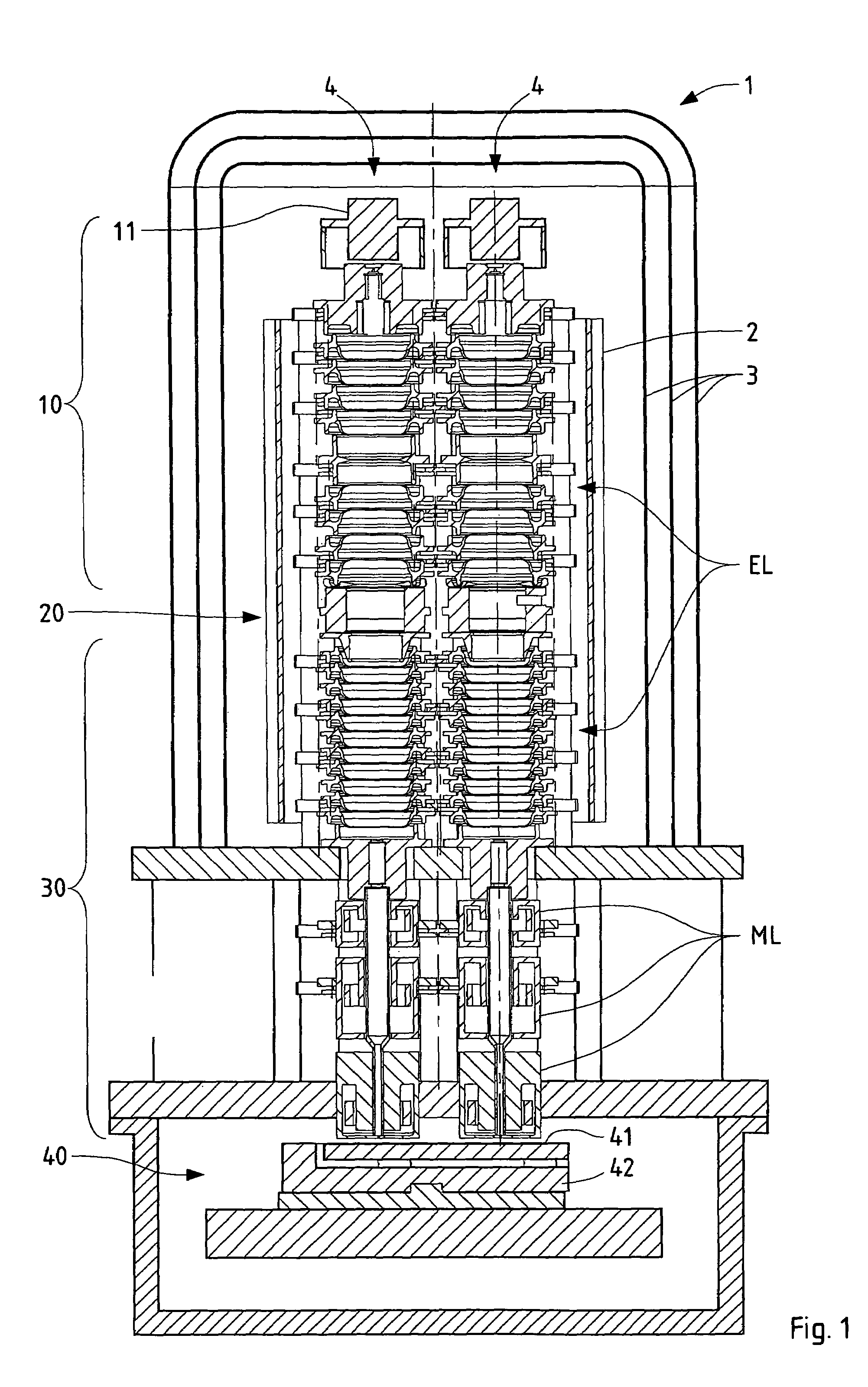
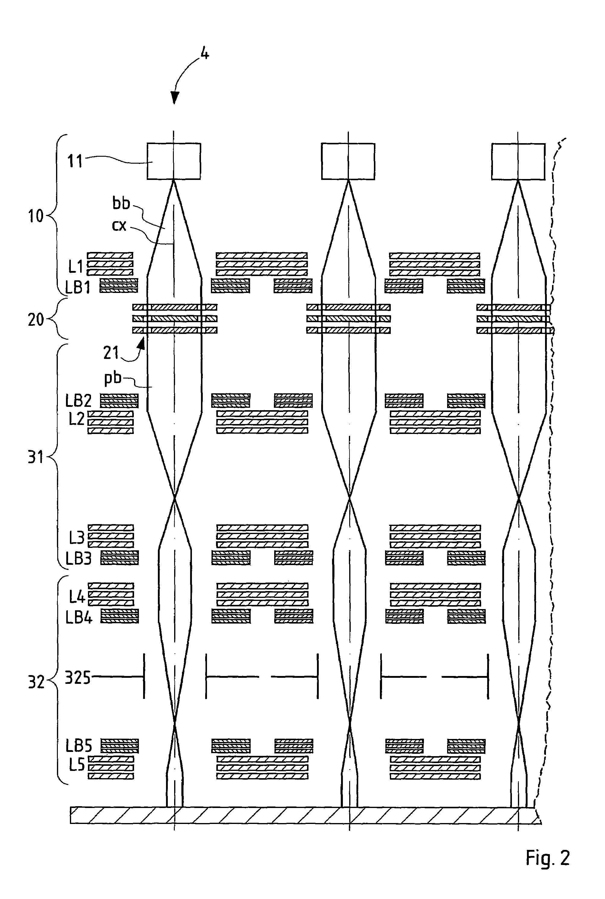
[0027]The basic idea of the present invention is to use several columns of a maskless particle-beam exposure apparatus, preferably of the kind as described in the U.S. Pat. No. 6,768,125, adapted to work in parallel on the same wafer in order to increase the throughput. As already explained, in the apparatus of the U.S. Pat. No. 6,768,125, a scanning stripe exposure technique is used for wafer exposures, the tool setup basically comprising a particle source, a charged particle projection system, realized by one optical column, and a dynamically generated image, transferred to a substrate at large demagnification. However, it should be appreciated that the apparatus disclosed in the U.S. Pat. No. 6,768,125 is not, as such, suitable for use in a multi-beam device; rather an modification is necessary. The modification comprises, in particular, the provision of common lens elements, as well as possibly further modifications, such as means for a reduced diameter of the columns, and an adapted wafer scanning strategy. The writing fields of each column do not overlap, so that each column exposes separate subfields of 1 / N area of the wafer, assuming N columns distributed regularly over the square-shaped area circumscribed around the wafer area. Thus, according to the invention several columns are working in parallel, realizing what may be called multiple scanning stripe exposure approach, bringing about unique advantages with respect to performance, reliability and tool fabrication costs, and avoiding physical limitations of charged particle optical systems based on single columns. It is emphasized that due to the unavoidable mechanical limitations of scanning stage systems, in particular of the stage velocity and acceleration (upper limits will be about 1–2 m / s and 30–40 m / s2, respectively) as well as jerk, in the high throughput regime, e.g. above 20 WPH, productivity is increased much faster than in a linear manner with the number of columns. The reason for this is that the total turn-around time (which is dead exposure time for the throughput) is significantly reduced with lower scanning speeds, achieved by the parallel use of several columns, at same acceleration and jerk.
[0028]In particular, the risk connected to the source reliability scales with the number of sources if each source is needed for writing the full pattern. Therefore, the number of sources should be kept low. In case of multiple scanning stripe exposure the risk connected to source reliability is largely reduced, as each column writes independently on one subfield (based on the total field being divided into a corresponding number of subfields), the subfield preferably comprising an integer number of chips, reducing the risk connected to the source to a factor of 1 / N (where N is the number of independent columns).
[0030]According to an advantageous variant of the invention the common lens elements may be realized individual lens elements provided for each of the particle beams and connected to a unique electrical supply. The common lens elements may also be realized by a common structural member surrounding each of the particle beams enhancing stability of the resulting structure.
[0033]In another advantageous development of the invention, the projection system comprises three or more focusing elements realizing reducing projection optics having two consecutive cross-overs. A reduction optics allows a pattern to be generated with very small feature sizes at the target.
[0035]In order to enhance the autonomy of the beams and facilitate generation of complex patterns a PD means may be provided for each particle beam, where the PD means has a pattern field in which the apertures are located, said pattern field having a length of at least 500 times the size of the apertures. Likewise, for each particle beam a pattern definition means may be provided with at least 20000 apertures whose transparency to the particle beam can be electronically controlled between switched on and off states.
[0036]An advantageous layout of the device realizes an electrostatic lens having an electrode column realized as a series of at least 3 electrodes of substantially equal shape of substantially rotational symmetry surrounding the respective beam path, with said electrodes being arranged in consecutive order coaxially along an optical axis representing the center of the beam path and said electrodes being provided with electric supplies for feeding different electrostatic potentials to the respective electrodes. This layout facilitates shielding out unwanted magnetic and electromagnetic fields from the beams.

Problems solved by technology

However, it should be appreciated that the apparatus disclosed in the U.S. Pat. No. 6,768,125 is not, as such, suitable for use in a multi-beam device; rather an modification is necessary.
In particular, the risk connected to the source reliability scales with the number of sources if each source is needed for writing the full pattern.

Method used


Image

  • Charged-particle multi-beam exposure apparatus
  • Charged-particle multi-beam exposure apparatus
  • Charged-particle multi-beam exposure apparatus

Examples


Embodiment Construction

[0054]A preferred embodiment of the invention is shown in FIG. 1. Four columns are combined in a 2×2 arrangement of a multicolumn apparatus 1 for exposing a wafer held in the target chamber representing the bottom of the apparatus. The longitudinal section of FIG. 1 runs through two neighboring columns 4. FIG. 2 shows a schematic longitudinal-section view illustrating the basic elements of the device of FIG. 1. (For the sake of clarity, the columns are shown in FIG. 2 as if they were arranged in a single plane.)

[0055]Major improvements of the embodiment over the prior art are, for example, that it offers a large redundancy in the pattern generation process on the one side, and an avoidance of alignment problems between different columns on the other side. It represents a novel implementation of multi-column and multi-beam (per column) approach, based on the above-mentioned U.S. Pat. No. 6,768,125. Furthermore, it allows to partially reduce or even circumvent technical risk issues in...


PUM

PropertyMeasurementUnit
currentsaaaaaaaaaa
velocityaaaaaaaaaa
energyaaaaaaaaaa

Abstract

A charged-particle multi-beam exposure apparatus (1) for exposure of a target (41) uses a plurality of beams of electrically charged particles, which propagate along parallel beam paths towards the target (41). For each particle beam an illumination system (10), a pattern definition means (20) and a projection optics system (30) are provided. The illuminating system (10) and / or the projection optics system (30) comprise particle-optical lenses having lens elements (L1, L2, L3, L4, L5) common to more than one particle beam. The pattern definition means (20) defines a multitude of beamlets in the respective particle beam, forming its shape into a desired pattern which is projected onto the target (41), by allowing it to pass only through a plurality of apertures defining the shape of beamlets permeating said apertures, and further comprises a blanking means to switch off the passage of selected beamlets from the respective paths of the beamlets.

Description

CROSS-REFERENCE TO RELATED APPLICATIONS[0001]This application claims the benefit of Austrian Patent Application Serial No. A 1660 / 2003, filed Oct. 20, 2003.FIELD OF THE INVENTION AND DESCRIPTION OF PRIOR ART[0002]The invention relates to a charged-particle multi-beam exposure apparatus used for forming a pattern on a surface of a target, such as a semiconductor substrate, by means of a set of beams of energetic electrically charged particles. More in detail, the invention relates to a charged-particle multi-beam exposure apparatus for exposure of a target with a plurality of beams of electrically charged particles, said particle beams propagating along parallel beam paths towards the target; for each of said particle beams an illumination system, a shaping means and a projection optics system are provided, with the illumination system being adapted to produce the beam and form it into a substantially telecentric beam illuminating the shaping means, the shaping means being adapted to...

Claims


Application Information

Patent Timeline
Patent Type & Authority Patents(United States)
IPC IPC(8): H01J37/08G21G5/00G03F7/20H01J37/317H01L21/027
CPCB82Y10/00B82Y40/00H01J37/3174H01J37/3177H01J3/06H01J37/08
Inventor STENGL, GERHARDPLATZGUMMER, ELMARLOSCHNER, HANS
Owner IMS NANOFABTION
Why Eureka
Try Eureka