

Chip-type solid electrolytic capacitor
a solid electrolytic capacitor and chip-type technology, applied in the field of capacitors, can solve the problem that the conventional chip-type solid electrolytic capacitor can only suppress esl to about 500 ph (picohenry)
- Summary
- Abstract
- Description
- Claims
- Application Information
AI Technical Summary
Benefits of technology
Problems solved by technology
Method used
Image

Examples
first embodiment
[0029]The first embodiment of the present invention is described below with reference to drawings.
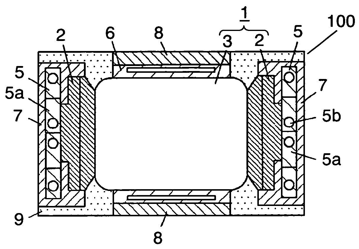
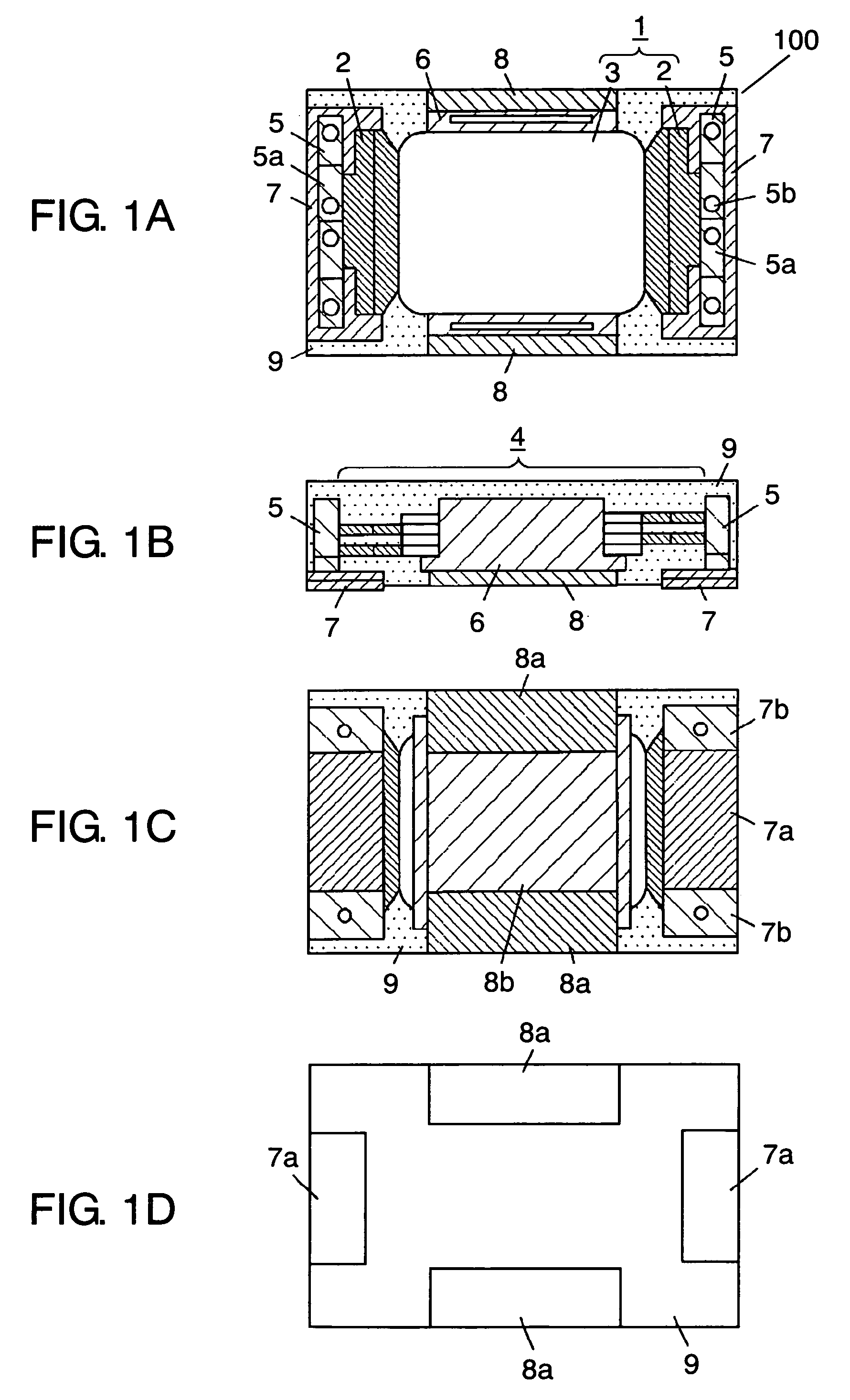
[0030]FIGS. 1A to 1D illustrate chip-type solid electrolytic capacitor 100 in the first embodiment of the present invention. In FIGS. 1A to 1D, capacitor element 1 has an anode body made of valve metal whose surface is roughened. The surface of the valve metal is provided with a dielectric oxide film which is formed by anodic oxidation (so called forming). A metal forming the oxide film on the surface by anodic oxidation is called a valve metal. Anode electrode 2 and a cathode forming area (not illustrated), separated by an insulating member (not illustrated), are created at a predetermined position of the anode body. A solid electrolytic layer made of conductive polymer is formed on the dielectric oxide film layer (not illustrated) at this cathode forming area. Then, a cathode layer (not illustrated), made of carbon and silver paste, is laminated on this solid electrolytic layer to for...
second embodiment
[0046]A chip-type solid electrolytic capacitor in the second embodiment has a partially different structure for the anode lead terminals and the cathode lead terminal from that described in the first embodiment. Other structures are the same as in the first embodiment, and thus for reasons of brevity the same parts are given the same reference numerals. Only parts that differ are described below with reference to drawings.
[0047]FIGS. 4A to 4D illustrate chip-type solid electrolytic capacitor 200 in the second embodiment. Chip-type solid electrolytic capacitor 200 includes anode lead terminals 11 and cathode lead terminal 12.
[0048]Each anode lead terminal 11 includes anode terminal 11a and thin sections 11b, the same as those in the first embodiment. Each thin section 11b is integrally covered with coating resin 9. As in the first embodiment, anode terminals 11a are exposed on the bottom face which becomes the mounting face. Conversely, each anode lead terminal 11 in the second embod...
third embodiment
[0052]Chip-type solid electrolytic capacitor 300 in the third embodiment has a partially different structure for the anode lead terminals and cathode lead terminal compared to chip-type solid electrolytic capacitor 200 described in the second embodiment. Other structure is the same as the second embodiment, and thus for reasons of brevity, parts are given the same reference numerals. Only parts that differ are described below with reference to drawings.
[0053]FIGS. 5A to 5E illustrate chip-type solid electrolytic capacitor 300 in the third embodiment. Chip-type solid electrolytic capacitor 300 includes anode lead terminals 13 to which anode lead frame 5 is bonded on its top face. Each anode lead terminal 13 includes bent sections 13b made by bending both ends of a single substrate in the width direction. A central section excluding these bent sections 13b acts as anode terminal 13a on mounting chip-type solid electrolytic capacitor 300. Each anode lead terminal 13 also includes protr...
PUM
| Property | Measurement | Unit |
|---|---|---|
| circumference | aaaaa | aaaaa |
| width | aaaaa | aaaaa |
| dielectric | aaaaa | aaaaa |
Abstract
Description
Claims
Application Information