Air bag door and attachment method

a technology for air bags and air bags, applied in the direction of couplings, manufacturing tools, and pedestrian/occupant safety arrangements, etc., can solve the problems of time-consuming and laborious removal of the cover from the housing, and the time-consuming and labor-intensive maintenance of the air bag module, so as to facilitate and facilitate the installation and removal of the cover. , the effect of facilitating the installation and removal of the cover

Inactive Publication Date: 2007-05-15
KEY SAFETY SYST
View PDF25 Cites 22 Cited by
  • Summary
  • Abstract
  • Description
  • Claims
  • Application Information

AI Technical Summary

Benefits of technology

[0006]The present invention comprises an air bag module having an air bag housing with an opening for deploying an air bag. A cover covers the opening. To simplify installation and removal of the cover, the air bag module has a straightforward connector comprising an aperture and a protrusion. Preferably, the protrusion is on the air bag housing while the aperture is on the cover. The protrusion may have three portions. The first portion extends from a surface of the air bag housing. The second and third portions extend transversely from the first portion. The first portion is disposed in the aperture with the second and third portions retaining the aperture on the first portion. The aperture may be larger than the first portion to allow the cover to move relative to the air bag housing. In this way, the air bag module provides some flexibility to accommodate off specification attachment points while still securing the cover to the air bag housing in two different directions.
[0007]In addition, the aperture of the connector flexes between a larger size opening and a smaller size opening. By being flexible, the aperture of the cover may be stretched over the protrusion during installation. The aperture then returns to a smaller dimension to secure itself around the protrusion. To disconnect the aperture from the protrusion, the aperture is stretched to the larger dimension and then taken off the protrusion. This design greatly facilitates installation and removal of the cover from the air bag housing.
[0008]Hence, the air bag cover may have an aperture that is stretched over a protrusion on the air bag housing. Once the protrusion is placed in this aperture, the aperture is allowed to reduce in size to thereby secure the cover to the air bag housing. The present invention accordingly allows for the quick installation and removal of the cover and provides greater flexibility in the installation of the air bag module into the vehicle.

Problems solved by technology

Due to the complexity of these connection features, the attachment of the cover to the air bag housing is time consuming.
In addition, these connection features make the removal of the cover from the housing difficult.
Accordingly, servicing the air bag module may also take too much time.
Because the cover and the housing are attached at different points, it may be difficult to install the air bag module into the vehicle if these mounting points are not where they should be.

Method used


Image

  • Air bag door and attachment method
  • Air bag door and attachment method
  • Air bag door and attachment method

Examples


Embodiment Construction

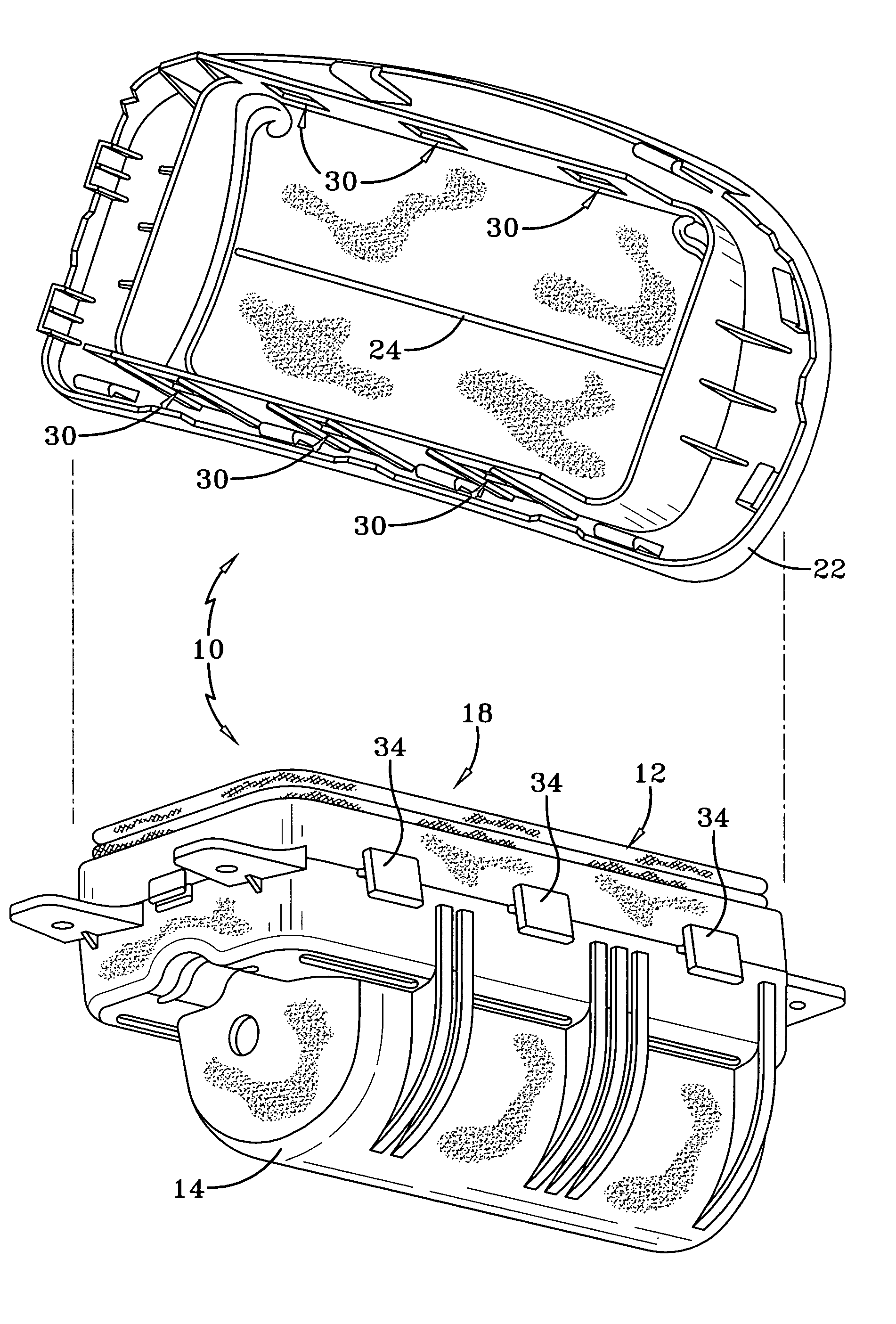
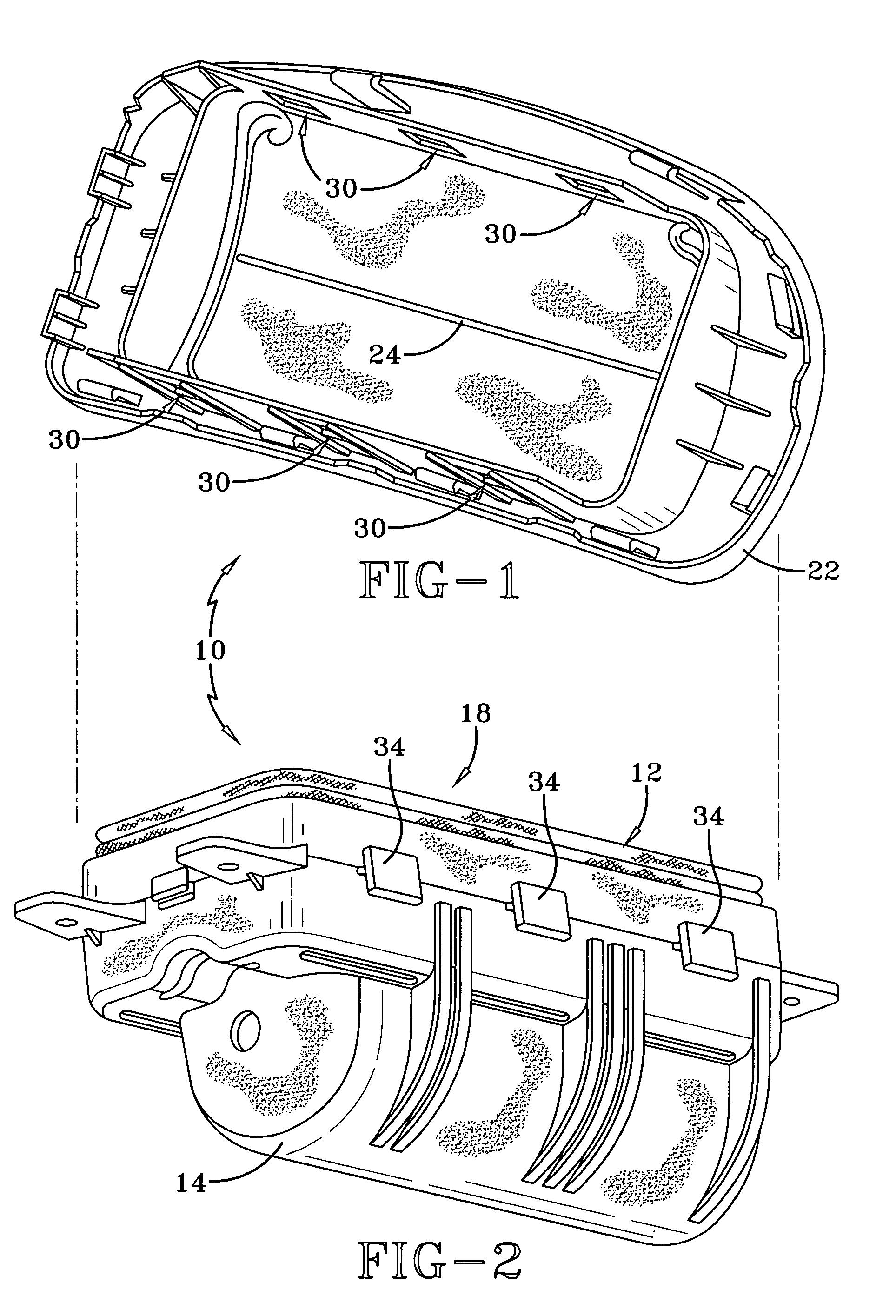
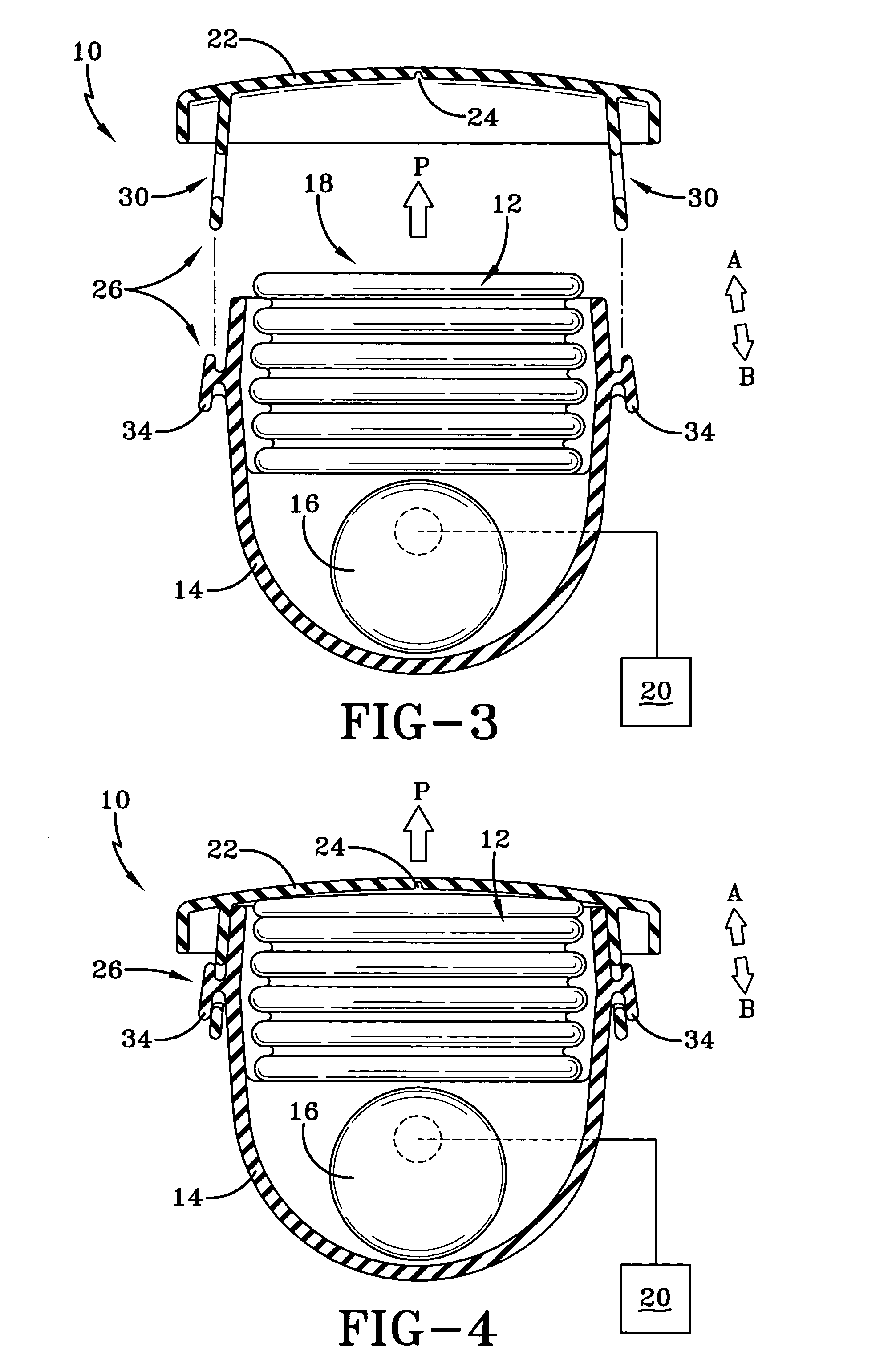
[0020]FIGS. 1–4 illustrate a view of the inventive air bag module 10. Air bag module 10 has an air bag cover 22 and an air bag housing 14. As shown in FIGS. 2–4, an air bag 12 is packed into the air bag housing 14. The air bag 12 is in communication with an air bag inflator 16, which is also disposed in the air bag housing 14. The air bag inflator 16 is controlled by a control unit 20 as known. Upon the detection of a vehicle crash of sufficient severity, air bag inflator 16 inflates the air bag 12 to cause its deployment in the direction of arrow P through an opening 18 of the air bag housing 14. As shown in FIGS. 1, 3 and 4, the air bag cover 22 has a tear seam 24 that allows the air bag 12 to pass through a tear of the air bag cover 22 during air bag deployment. These features of the invention are well known.

[0021]In the past, the air bag cover 22 was attached to the air bag housing 14 by complicated connectors, such as brackets or rivets. Although these type of connection featur...


PUM


Abstract

An air bag module has an air bag housing with an opening for deploying the air bag. The opening is provided with the cover. A connector attaches the cover to the air bag housing. The connector has an aperture and a protrusion for engaging the aperture. The aperture is located on one of the air bag housing and the cover while the protrusion is located on the other of the air bag housing and the cover. The protrusion has a first portion, a second portion and a third portion. The first portion extends from a surface of one of the air bag housing and the cover while the second portion extends transversely from the first portion and the third portion extends transversely from the first portion.

Description

BACKGROUND OF THE INVENTION[0001]This invention relates to an air bag module.[0002]An air bag module for a vehicle typically has an air bag and an air bag inflator. The air bag and air bag inflator are located in an air bag housing, which is mounted to a part of the vehicle. The housing has an opening through which the air bag deploys. A cover is placed over this opening. The cover may have a tear seam that tears when the air bag inflates to allow the air bag to deploy through the torn cover of the housing.[0003]The cover is usually attached to the housing by rivets, brackets or other complicated connection features. The connection feature must securely attach the cover to housing. Due to the complexity of these connection features, the attachment of the cover to the air bag housing is time consuming. In addition, these connection features make the removal of the cover from the housing difficult. Accordingly, servicing the air bag module may also take too much time.[0004]Moreover, w...

Claims


Application Information

Patent Timeline
Patent Type & Authority Patents(United States)
IPC IPC(8): B60R21/215B60R21/217
CPCB60R21/2171Y10T403/7123Y10T403/7015B60R2021/2172B60R21/201B60R21/2165
Inventor BAUMBACH, ERICHILLAKER, JOSEPHMANN, RAVINDER
Owner KEY SAFETY SYST
Why Eureka
Try Eureka