Holey mirror arrangement for dual-energy e-beam inspector

a dual-energy, beam-emitting technology, applied in the direction of magnetic discharge control, instruments, therapy, etc., can solve the problems of high surface voltage, affecting imaging, and affecting the imaging effect of electron beams

Inactive Publication Date: 2007-05-15
KLA TENCOR TECH CORP
View PDF8 Cites 16 Cited by
  • Summary
  • Abstract
  • Description
  • Claims
  • Application Information

AI Technical Summary

Benefits of technology

[0009]One embodiment pertains to an apparatus for generating a dual-energy electron beam. A first electron beam source is configured to generate a lower-energy electron beam, and a second electron beam source is configured to generate a higher-energy electron beam. A holey mirror is biased to reflect the lower-energy electron beam. The holey mirror also includes an opening therein through which passes the higher-energy electron beam, thereby forming the dual-energy...

Problems solved by technology

Unfortunately, surface charging effects can pose a difficulty for electron beam imaging of insulating surfaces (whether scanned or direct imaging).
The high current densities required for imaging at inspection rates imply a like...

Method used


Image

  • Holey mirror arrangement for dual-energy e-beam inspector
  • Holey mirror arrangement for dual-energy e-beam inspector
  • Holey mirror arrangement for dual-energy e-beam inspector

Examples


Embodiment Construction

[0019]Two Electron Guns with Inclined Beam Axes

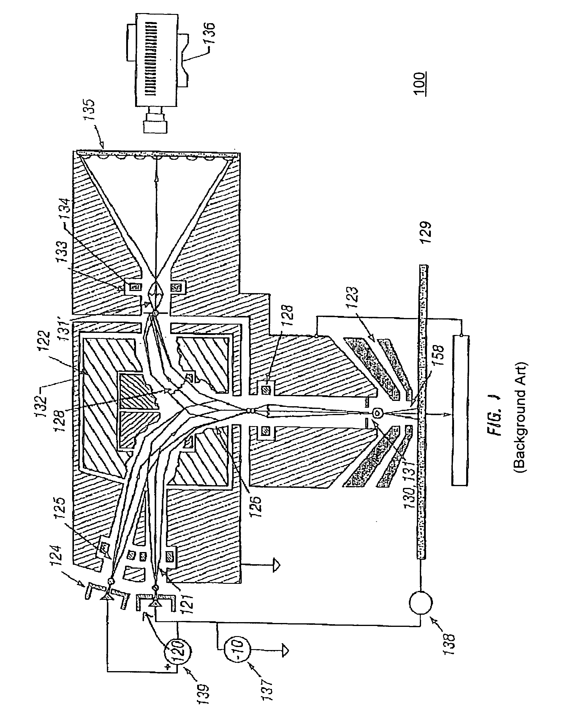
[0020]FIG. 1 is a diagram depicting a structure for a first prior e-beam apparatus 100 having two illuminating beams. This prior apparatus 100 is described in International Publication Number WO 01 / 88514 A1, “Apparatus for Inspection of Semiconductor Wafers and Masks Using a Low Energy Electron Microscope with Two Illuminating Beams,” applicant KLA-Tencor Corporation, inventors Lee Veneklasen, David L. Adler, and Matthew Marcus, published Nov. 22, 2001.

[0021]In this prior apparatus 100, a first electron gun 120 generates a low energy beam 121, and a second electron gun 124 generates a higher energy beam 125. The electron gun 120 for the low energy beam 121 inserts this beam into the illumination portion of a magnetic separator 122, where it is bent into the axis of the cathode (objective) lens 123. The second gun 124 is located slightly above and behind the low energy gun 120. Since its energy is somewhat higher, the beam 125 from the s...


PUM


Abstract

One embodiment relates to an apparatus for generating a dual-energy electron beam. A first electron beam source is configured to generate a lower-energy electron beam, and a second electron beam source is configured to generate a higher-energy electron beam. A holey mirror is biased to reflect the lower-energy electron beam. The holey mirror also includes an opening therein through which passes the higher-energy electron beam, thereby forming the dual-energy electron beam. A prism array combiner introduces a first dispersion between the lower-energy electron beam and the higher-energy electron beam within the dual-energy electron beam. A prism array separator is configured to separate the dual-energy electron beam traveling to a substrate from a scattered electron beam traveling away from the substrate. The prism array separator introduces a second dispersion which compensates for the dispersion of the prism array combiner. Other embodiments are also disclosed.

Description

CROSS-REFERENCE TO RELATED APPLICATIONS[0001]The present invention claims the benefit of U.S. Provisional Patent Application No. 60 / 705,312, entitled “Holey Mirror Arrangement for Dual-Energy E-Beam Inspector,” filed Aug. 3, 2005 by inventors Marian Mankos and Eric Munro, the disclosure of which is hereby incorporated by reference.GOVERNMENT LICENSE RIGHTS[0002]The U.S. Government has a paid-up license in this invention and the right in limited circumstances to require the patent owner to license others on reasonable terms as provided for by the terms of Contract No. DAAD 19-00-3-1001 awarded by the U.S. Army Research Laboratory.BACKGROUND OF THE INVENTION[0003]1. Field of the Invention[0004]The present invention relates generally to electron beam (e-beam) apparatus and e-beam inspection methods.[0005]2. Description of the Background Art[0006]Most conventional wafer and mask inspection systems use light optical images. Scanning electron beam microscopes (SEMs) have also been develop...

Claims


Application Information

Patent Timeline
IPC IPC(8): H01J37/26G01N23/225
CPCH01J37/05H01J37/147H01J37/153H01J37/26H01J37/29H01J2237/0044H01J2237/063H01J2237/151H01J2237/2446H01J2237/262
Inventor MANKOS, MARIANMUNRO, ERIC
Owner KLA TENCOR TECH CORP
Why Eureka
Try Eureka