
Wind energy system, as well as a method for operating such a wind energy system

a wind energy system and wind energy technology, applied in the direction of electric generator control, machines/engines, mechanical apparatus, etc., can solve the problems of small circuitry complexity and occupies little space, and achieves the effect of simple and robust, implemented with little circuitry complexity, and simple and efficient manner

Active Publication Date: 2007-05-15
ABB (SCHWEIZ) AG
View PDF6 Cites 12 Cited by
  • Summary
  • Abstract
  • Description
  • Claims
  • Application Information

AI Technical Summary

Benefits of technology

[0004]The object of the invention is therefore to specify a wind energy system in which a rectifier unit which is connected to a generator in the wind energy system can be selectively disconnected from the wind energy system if it fails and / or becomes defective, with continued operation of the remaining components of the wind energy system without interruption being possible, and which is particularly simple and robust and can be implemented with little circuitry complexity. It is also intended to specify a method by means of which the wind energy system according to the invention can be operated in a particularly simple and efficient manner.
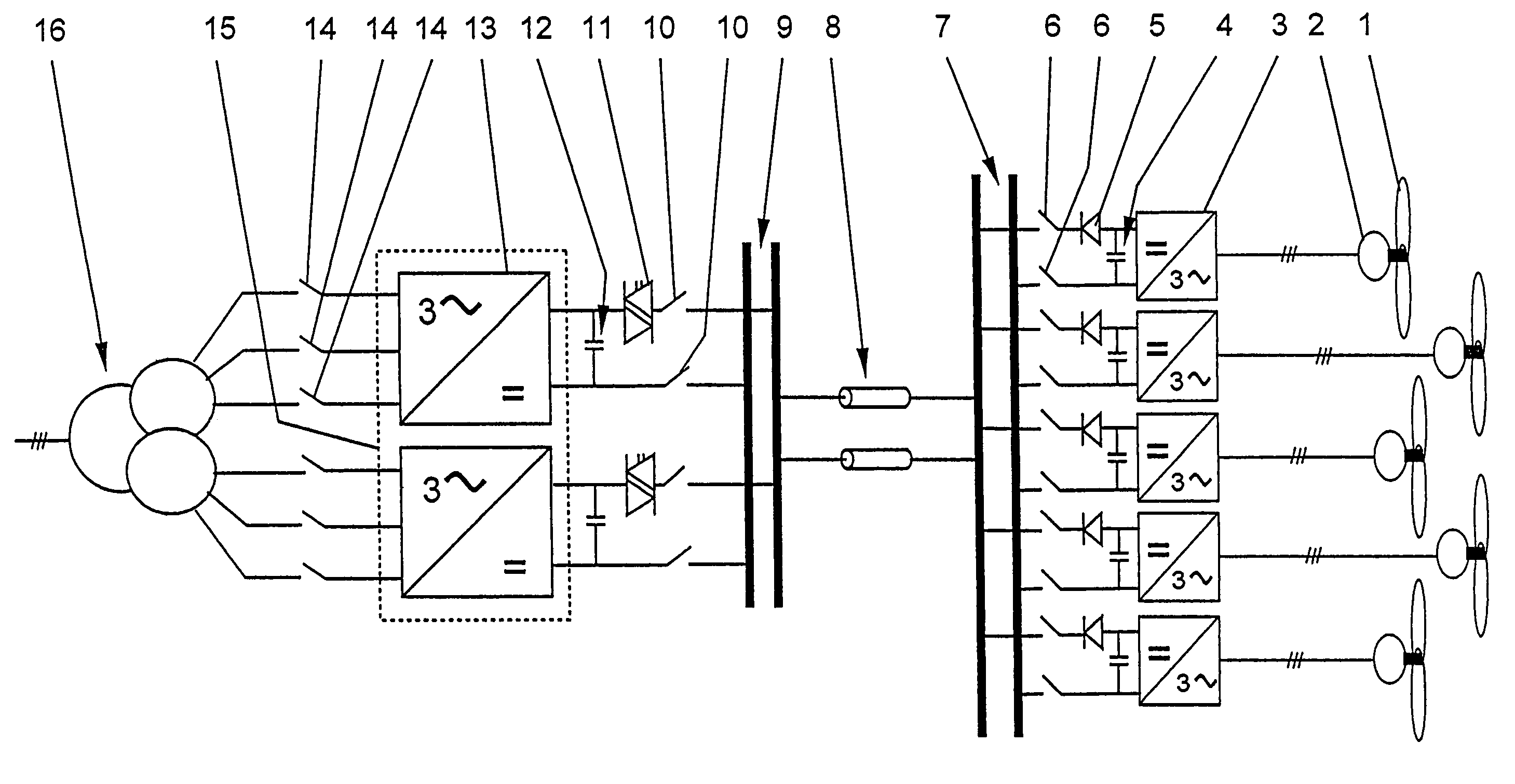
[0005]The wind energy system according to the invention comprises at least two generators which are driven by means of wind rotors, with a rectifier unit being provided for each generator, to whose inputs the associated generator is connected. Furthermore, the wind energy system has an energy storage circuit for each rectifier unit, with the energy storage circuit being connected to the outputs of the associated rectifier unit. A first busbar system is also provided, to which the energy storage circuits are connected in parallel. The first busbar system is connected to a transmission system, with a network coupling device being provided, to which the transmission system is connected on the input side. Furthermore, the network coupling device is coupled via a network transformer to an electrical AC voltage supply network. According to the invention, each rectifier unit is in the form of an active rectifier unit with drivable power semiconductor components. Furthermore, each energy storage circuit has at least one DC voltage capacitance and, in at least one connection for the first busbar system, at least one first protection switch in the form of a semiconductor switch. The active rectifier unit and the energy storage circuit together with the DC voltage capacitance advantageously make it possible to set a variable, load-independent DC voltage for the energy storage circuit. In consequence, the voltage of the transmission system which (as mentioned above) is connected via the first busbar system to the energy storage circuits can be increased, so that the electrical power loss can advantageously be reduced, in particular in a transmission system which, for example, extends over a long distance. Furthermore, in the event of a defect and / or a failure of one or more rectifier units, a current flow which is greater than the maximum permissible current value from the first busbar system to the respective energy storage circuit and / or a current flow from the energy storage circuit to the first busbar system can be interrupted by the respective first protection switch in a desirable manner. This interruption results in fast, selective disconnection of the appropriate rectifier unit from the wind energy system, thus advantageously allowing continued operation, without any interruption, of the remaining components of the wind energy system. The first protection switch, in the form of a semiconductor switch, in this case advantageously remains undamaged and is not destroyed.
[0006]Furthermore, the wind energy system requires only a minimum number of components and, in particular owing to the use of the DC voltage capacitances for the energy storage circuits, occupies little space and can be implemented with a small amount of circuitry complexity. Furthermore, by virtue of its simple design and the small number of components, the wind energy system according to the invention is highly convenient for maintenance and repair and, furthermore, is very robust.
[0007]In the method according to the invention for operating the wind energy system, electrical energy for feeding to the electrical AC voltage supply network is produced by the at least two generators which are driven by means of wind rotors. According to the invention, when a defect and / or failure occurs in one of the rectifier units, the associated first protection switch or switches is or are opened. Since the associated first protection switch or switches is or are opened in the event of a defect or failure of a rectifier unit, the corresponding rectifier unit is disconnected easily and quickly from the wind energy system, so that the wind energy system can advantageously continue to operate, without any interruption. The method according to the invention thus allows particularly efficient operation of the wind energy system, and, furthermore, particularly high wind energy system availability can be achieved.

Problems solved by technology

Furthermore, the wind energy system requires only a minimum number of components and, in particular owing to the use of the DC voltage capacitances for the energy storage circuits, occupies little space and can be implemented with a small amount of circuitry complexity.

Method used


Image

  • Wind energy system, as well as a method for operating such a wind energy system
  • Wind energy system, as well as a method for operating such a wind energy system

Examples


Embodiment Construction

[0012]The FIGURE shows one embodiment of a wind energy system according to the invention. The wind energy system comprises at least two generators 2 which are driven by means of wind rotors 1. Furthermore, a rectifier unit 3 is provided for each of these generators 2, to whose inputs, in particular AC voltage inputs, the associated generator 2 is connected. Each rectifier unit 3 has an energy storage circuit 4, which is connected to outputs, in particular to DC voltage outputs, of the associated rectifier unit 3. As shown in the FIGURE, all the energy storage circuits 4 are connected in parallel to a first busbar system 7, with a transmission system 8 also being connected to the first busbar system 7. Furthermore, as shown in the FIGURE, a network coupling device 15 is provided, to which the transmission system 8 is connected on the input side. As shown in the FIGURE, the network coupling device 15 is coupled via a network transformer 16 to an electrical AC voltage supply network, a...


PUM


Abstract

Systems and methods of the present invention are directed to wind energy. Wind rotors (1) drive at least two generators (2) which each have a corresponding rectifier unit (3). The rectifier unit (3) being an active rectifier having drivable power semiconductor components. An energy storage circuit (4) is associated with each rectifier unit (3) and is connected in parallel to a first busbar system (7). Each energy storage circuit (4) having at least one DC voltage capacitance, and the first busbar system (7) having a first protection switch (5) in at least one connection.

Description

FIELD OF THE INVENTION[0001]The invention relates to the field of wind energy systems and is based on a wind energy system and a method for operating such a system.BACKGROUND OF THE INVENTION[0002]Wind energy systems, which are now being used increasingly as alternative energy sources as energy resources disappear, are normally set up on land or at sea, close to the coast. One such wind energy system is disclosed in WO 00 / 74198 A1. The wind energy system has at least two wind rotors, with each rotor being mechanically connected to a generator, which it drives. Each of the generators is connected to an associated passive rectifier unit. All the rectifier units also have an energy storage circuit on their DC voltage sides, with each energy storage circuit being formed by appropriate inductances. However, due to their large and complex structure, these inductances result in additional material costs and require a correspondingly large amount of space. Each energy storage circuit is fol...

Claims


Application Information

Patent Timeline
Patent Type & Authority Patents(United States)
IPC IPC(8): H02J3/00F03D9/02H02H7/06F03D9/25H02J3/36H02J3/38H02P9/00H02P9/48
CPCF03D9/005H02J3/36H02J3/386Y02E10/725Y02E10/763H02M7/493F03D9/257H02J2300/28H02J3/381Y02E10/76Y02E10/72H02M1/325
Inventor STEINKE, JURGEN
Owner ABB (SCHWEIZ) AG
Learn More