Liquid crystal display and computer

a liquid crystal display and computer technology, applied in the field of liquid crystal display and computer, can solve the problems of image quality deterioration, slow response speed of liquid crystal material, and inability to complete variation of gradation in one field period

Inactive Publication Date: 2007-05-15
RENESAS ELECTRONICS CORP
View PDF25 Cites 20 Cited by
  • Summary
  • Abstract
  • Description
  • Claims
  • Application Information

AI Technical Summary

Benefits of technology

[0115]Further, the display control circuit is provided to control so that a part or the whole of a dynamic image is turned to be a single color for a predetermined time based upon whether a displayed image is a dynamic image or a static image. Therefore, dim movement may be prevented.
[0115]Further, the display control circuit is provided to control so that a part or the whole of a dynamic image is turned to be a single color for a predetermined time based upon whether a displayed image is a dynamic image or a static image. Therefore, dim movement may be prevented.
[0116]When a static image is displayed, the display control circuit performs line-sequential driving, instead of turning a part of a static image or a whole of a static image into a single color. Therefore, the deterioration of image quality such as a flicker may be prevented. In addition, the deterioration of display luminance may also be prevented. As a result, as the luminance of the backlight is not required to be set to a high value, wasteful power consumption can be prevented.

Problems solved by technology

In case a dynamic image is displayed on this LCD, a problem occurs in that the image quality deteriorates due to causes such as a residual image phenomenon.
The cause of this deterioration is thought to be because the speed of a response of liquid crystal material is slow.
As a result, when gradation varies, the variation of gradation cannot be completed in one field period and an accumulative response is performed in a few field periods.
However, it has been reported that the above-mentioned problems such as the residual image phenomenon are not caused by only the speed of the response of liquid crystal, but are also caused by the methods used to change the image displayed on LCD.
However, when a dynamic image is displayed on LCD, an image currently displayed is viewed in a state in which it, and an image displayed immediately before it, are overlapped due to the visual time integral effect and other effects, causing movement to become dim.
This difference in display time causes a problem in that luminance difference depends upon the location on the liquid crystal display panel 114 as shown in an example in FIG. 7C.
However, the deterioration of image quality such as a flicker occurs due to a black screen inserted also in the display of a static image, both in the method shown in FIGS. 7A and 7C and in the device shown in FIG. 8, even though a hold-type display is suited for the display of the static image.
This increase in the luminescence of the back light increases power consumption, which is also a problem.

Method used


Image

  • Liquid crystal display and computer
  • Liquid crystal display and computer
  • Liquid crystal display and computer

Examples


first embodiment

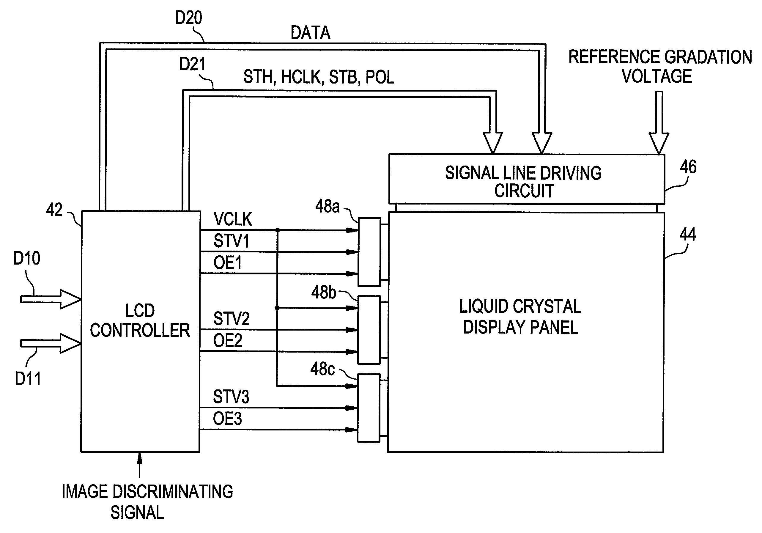
[0070]FIG. 9 is a functional block diagram showing the schematic structure of a liquid crystal display according to a first illustrative, non-limiting embodiment of the present invention. In the first embodiment as shown in FIG. 9, a computer 30 such as a personal computer and the liquid crystal display 40 are separately provided. The computer 30 outputs gradation data D10, synchronism data D11 and an image discriminating signal J1 to the liquid crystal display 40.

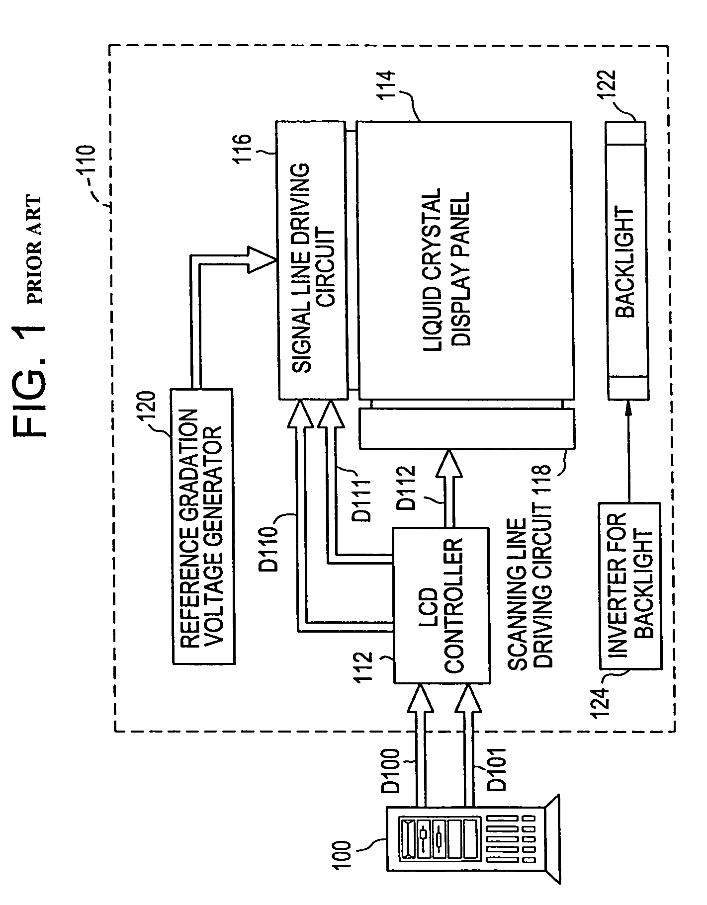
[0071]The gradation data D10 and the synchronism data D11 are respectively similar signals to gradation data D100 and synchronism data D101 shown in FIG. 1. For example, the gradation data D10 is an RGB signal, and the synchronism data D11 is data including a vertical synchronizing signal, a horizontal synchronizing signal, a data enable signal (DE) and a clock. The image discriminating signal J1 is a signal of one bit showing whether image data (a signal composed of the gradation data D10 and the synchronism data D11) out...

second embodiment

[0101]That is, when the dynamic image is displayed in a window, which is not a whole of the liquid crystal display panel 44, but is a part of the liquid crystal display panel 44, dim movement is not perceived so much, as long as the part of the liquid display panel 44 is proper size. That is because difference between the amount of the movement of a dynamic image and the following kinetic competence of a person's eye is small. Then, in the present invention, the criterion of a display method of a liquid crystal display and the judgment of whether a backlight is controlled or not is based upon the area ratio of a liquid crystal display panel 44 and a window in which a dynamic image is displayed. That is, in case the area ratio of the liquid crystal display panel 44 and a window in which a dynamic image is displayed is a certain threshold or more, an image displayed on the liquid crystal display panel 44 is judged to be a dynamic image and an image discriminating signal J1 is turned t...

third embodiment

[0110]In the above-mentioned third embodiment, it is judged whether image data is a dynamic image or not based upon whether there is movement in two frames or not. However, the storage capacity of the frame memory 62 may be increased to store the image data of plural frames, and the plural frames may be compared in order to judge whether image data is a dynamic image or not.

[0111]In the above-mentioned third embodiment, image data is considered to be a dynamic image when there is any movement between frames. Therefore, an image discriminating signal J1 may be turned to a high level even if a display area where a dynamic image is displayed is so small that it might not necessary to control the LCD controller 112 as described in the first embodiment. Then, a frame may be divided in to a plurality of blocks, which is a detection area, and it may be detected how many detection areas have movement, instead of comparing whole frames. When a number of detection areas which have movement is...


PUM

PropertyMeasurementUnit
areaaaaaaaaaaa
brightnessaaaaaaaaaa
coloraaaaaaaaaa

Abstract

A backlight control circuit that variably controls the display luminance of a liquid crystal display panel by controlling the luminance of a backlight based upon whether an image displayed on the liquid crystal display panel is a dynamic image or a static image, and an LCD controller that controls so that a part or the whole of a dynamic image is displayed by using a single color for a predetermined time in case an image displayed on the liquid crystal display panel is a dynamic image are provided.

Description

BACKGROUND OF THE INVENTION[0001]1. Field of the Invention[0002]The present invention generally relates to a liquid crystal display and a computer, particularly but not limited to, an active matrix liquid crystal display suitable for the display of a dynamic image and a computer suitably used with the liquid crystal display. The present application is based on Japanese Patent Application No. 314274 / 2000, which is incorporated herein by reference.[0003]2. Description of the Related Art[0004]Recently, the display screen of a liquid crystal display (LCD) has been enlarged and the definition has been enhanced. A displayed image ranges from a static image as in a liquid crystal display used for a personal computer, a word processor and the like, to a dynamic image as in a liquid crystal display used for TV and the like. Since the compression technology for dynamic images has progressed and a dynamic image can now be also easily handled in a computer, a frequency at which a dynamic image ...

Claims


Application Information

Patent Timeline
Patent Type & Authority Patents(United States)
IPC IPC(8): G09G3/36G02F1/133G09F9/00G09G3/20G09G3/34H04N5/66
CPCG09G3/3406G09G3/3611G09G3/3648G09G2310/0251G09G2310/061G09G2320/0261G09G2320/062G09G2320/0633G09G2320/106G02F1/133
Inventor NOSE, TAKASHI
Owner RENESAS ELECTRONICS CORP
Why Eureka
Try Eureka