Magnetic media patterning via contact printing utilizing stamper having magnetic pattern formed in non-magnetic substrate

Inactive Publication Date: 2007-05-15
SEAGATE TECH LLC
View PDF8 Cites 54 Cited by
  • Summary
  • Abstract
  • Description
  • Claims
  • Application Information

AI Technical Summary

Benefits of technology

[0030]An advantage of the present invention is an improved method of manufacturing a stamper/imprinter for use in forming a magnetic transition pattern in a magnetic material by means of contact printing.
[0031]Another advantage of the present invention is an improved method of manufacturing a stamper/imprinter for use in forming a servo pattern in a magnetic recording medium by means of contact printing.
[0032]A further advantage of the present invention is an improved stamper/imprinter for performing contact printing of a magnetic transition pattern in a

Problems solved by technology

Because of the locational precision needed, writing of servo patterns requires expensive servo-pattern writing equipment and is a time consuming process.
However, the above-described method incurs several drawbacks associated with its implementation in an industrially viable manner.
Specifically, a “one-of-a-kind” master writer with a very high write field gradient is necessary for writing the requisite high intensity, master magnetic servo pattern onto the master disk, and a complicated means for rotating the aligned master servo-writer disk and “slave” workpiece magnetic dis

Method used


Image

  • Magnetic media patterning via contact printing utilizing stamper having magnetic pattern formed in non-magnetic substrate
  • Magnetic media patterning via contact printing utilizing stamper having magnetic pattern formed in non-magnetic substrate
  • Magnetic media patterning via contact printing utilizing stamper having magnetic pattern formed in non-magnetic substrate

Examples


Example

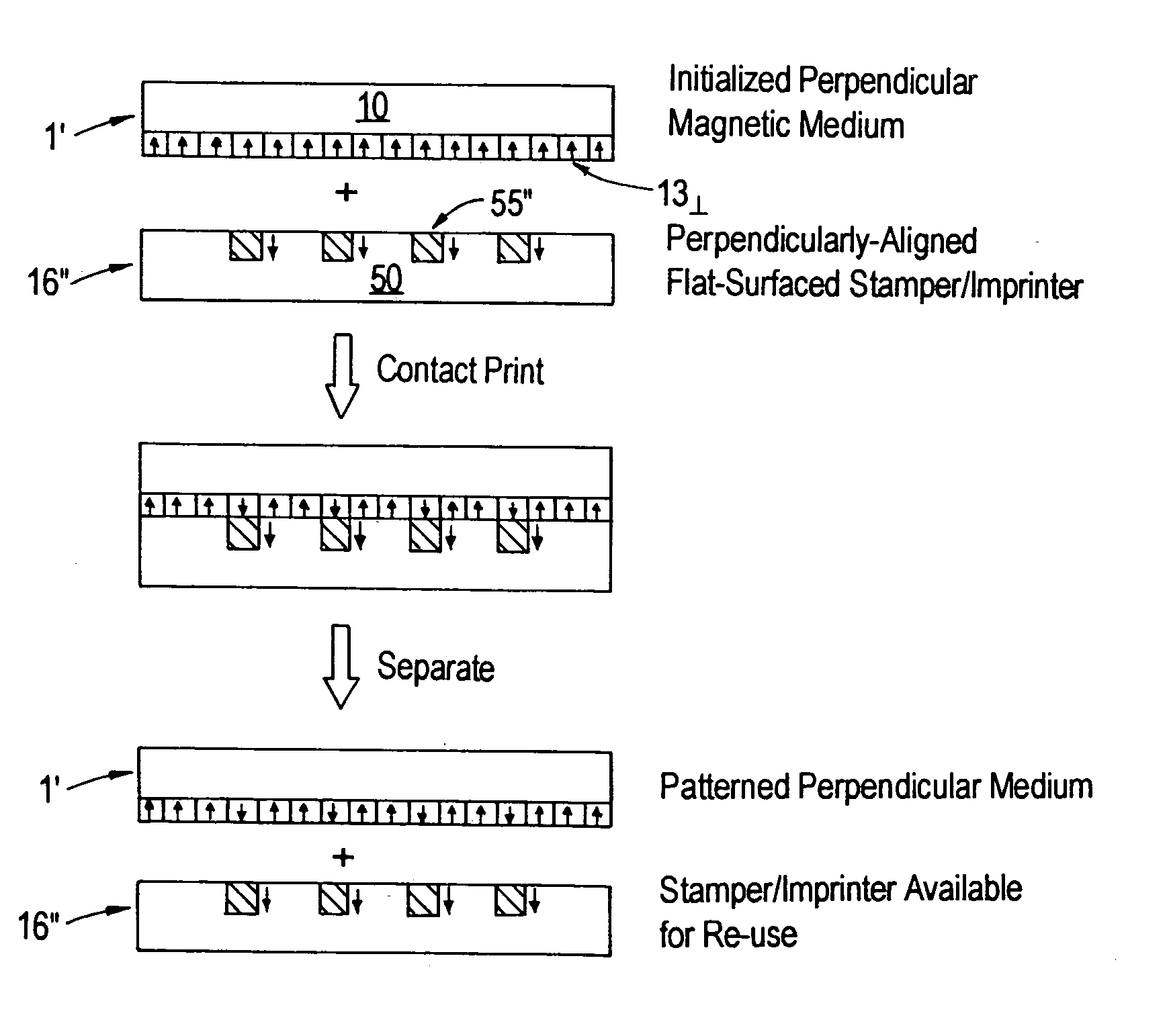
[0087]The present invention addresses and solves problems and drawbacks attendant upon the use of stampers / imprinters with topographically patterned imprinting surfaces in performing high replication quality contact printing of recording layers of magnetic recording media for forming magnetic patterns therein, e.g., servo patterns, in a cost-efficient manner at high product throughput rates. Specifically, the present invention is based upon the discovery by the inventors that modification of the imprinting surface of the stamper / imprinter to eliminate the conventional topographical patterning thereof can provide a number of significant advantages, including, inter alia: (1) process simplification, as by eliminating the need for application of an external magnetic re-alignment field during the imprinting process; and (2) more rapid and more easily controllable processing of workpieces / substrates.

[0088]Key features of the present invention are the manufacture and use of improved stamp...


PUM

PropertyMeasurementUnit
Magnetismaaaaaaaaaa

Abstract

A stamper/imprinter for use in forming a magnetic transition pattern in a magnetic material by means of contact printing, comprising: (a) a non-magnetic substrate having a major surface comprising a patterned plurality of spaced-apart recesses with a plurality of non-recessed areas therebetween, the patterned plurality of recesses corresponding to the magnetic transition pattern to be formed in the magnetic material; and (b) unidirectionally permanently magnetized material filling each of the plurality of recesses and having exposed surfaces substantially coplanar with the plurality of non-recessed areas.

Description

CROSS-REFERENCE TO PROVISIONAL APPLICATION[0001]This application claims priority from U.S. provisional patent application Ser. No. 60 / 392,986 filed Jun. 28, 2002, the entire disclosure of which is incorporated herein by reference.FIELD OF THE INVENTION[0002]The present invention relates to methods and devices for forming magnetic transition patterns in a layer or body of magnetic material. The invention has particular utility in the formation of servo patterns in the surfaces of magnetic recording layers of magnetic data / information storage and retrieval media, e.g., hard disks.BACKGROUND OF THE INVENTION[0003]Magnetic recording media are widely used in various applications, e.g., in hard disk form, particularly in the computer industry for storage and retrieval of large amounts of data / information in magnetizable form. Such media are conventionally fabricated in thin film form and are generally classified as “longitudinal” or “perpendicular”, depending upon the orientation (i.e., p...

Claims


Application Information

Patent Timeline
Owner SEAGATE TECH LLC
Why Eureka
Try Eureka