Exposure dose control of rotating electron beam recorder

a technology of electron beam and exposure dose, which is applied in the direction of photomechanical equipment, maintaining head carrier alignment, instruments, etc., can solve the problems of affecting spot size, affecting spot size, and unwanted variation in feature geometry, so as to achieve uniform exposure dose

Inactive Publication Date: 2007-05-15
SEAGATE TECH LLC
View PDF6 Cites 13 Cited by
  • Summary
  • Abstract
  • Description
  • Claims
  • Application Information

AI Technical Summary

Benefits of technology

[0015]The concepts disclosed herein alleviate the above noted problems with using a stationary beam in combination with disk rotation and translation to produce servo patterns or the like on a disk work piece, by controlling the exposure to compensate for variations in relative speed or velocity. In a constant angular velocity (CAV) type process, the exposure compensates for the linear velocity variation due to different radial distances from the center of rotation. As a result, the beam lithography processing can produce substantially uniform exposure dosages.

Problems solved by technology

However, application of beam lithography to rotating disk shaped work pieces presents certain problems, as will be discussed below.
Such variation in dosage results in unwanted variation in the feature geometry.
Unfortunately, variation of the beam current adversely affects the spot size and again produces unwanted changes in the recorded feature geometry.

Method used


Image

  • Exposure dose control of rotating electron beam recorder
  • Exposure dose control of rotating electron beam recorder
  • Exposure dose control of rotating electron beam recorder

Examples


Embodiment Construction

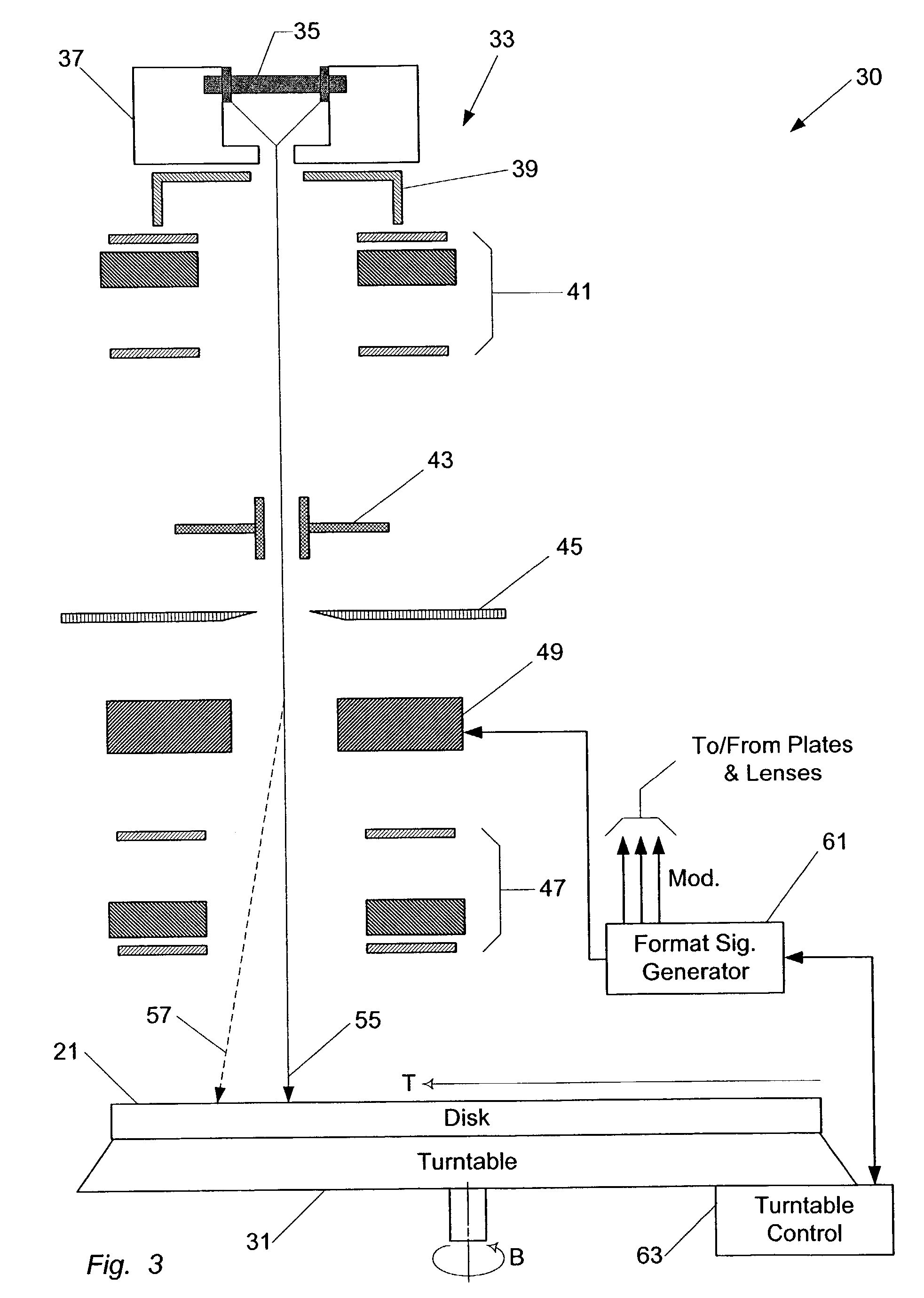
[0036]The concepts disclosed herein address and solve problems related to providing beam exposure patterns on a disk medium, with uniform exposure dose, for example, as used for forming servo patterns or the like on a disk work piece. In the examples, beam modulation sub-pulse duty cycle is controlled in accord with radial distance and / or linear speed relative to the exposure beam.

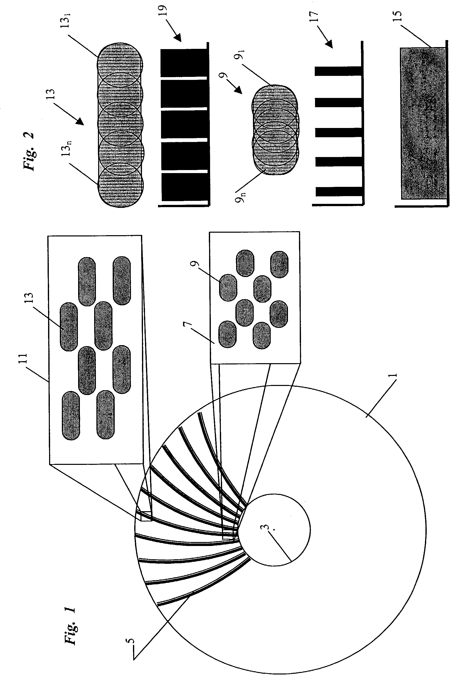
[0037]Reference now is made in detail to the examples illustrated in the accompanying drawings and discussed below. FIG. 1 illustrates a pattern of exposure of servo marks formed by beam lithography on a surface of a disk work piece 1. Although the electron beam recording technology may be used on other types of disks, for discussion purposes, the example of disk 1 is a resist coated silicon wafer as might be used as a master disk for hard drive media manufacture. The disk 1 has an inner opening 3 defining the inner diameter (ID) of the recording surface. The outer periphery of the disk 1 defines an outer ...


PUM

PropertyMeasurementUnit
ODaaaaaaaaaa
frequencyaaaaaaaaaa
frequencyaaaaaaaaaa

Abstract

In a beam lithography operation the relative motion between a work piece and the exposure beam produces variations in linear speed at different regions of the work piece surface. For example, if a disk work piece rotates with a constant angular velocity (CAV) relative to the beam, the linear surface speed relative to the beam impact point increases in proportion to increasing radial distance of that point from the center of the disk. To provide uniform exposure dose, the duty cycle of pulses of the exposure beam are varied in accord with radial distance.

Description

RELATED APPLICATION[0001]This application claims the benefit of U.S. Provisional Application No. 60 / 385,521 entitled “Exposure Control of Rotating Electron Beam Recorder” filed on Jun. 3, 2002, the disclosure of which is entirely incorporated herein by reference.FIELD OF THE INVENTION[0002]The present subject matter relates to techniques and equipment for using beam lithography to lay down patterns on a disk medium, for example, for tracks of servo patterns to be formed on a surface of a master for the production of a magnetic disk of a hard disk drive, where the exposure energy is controlled to compensate for differences in speed of the disk surface relative to the exposure beam during the track forming process by moderating the energy of the beam to insure uniform exposure dose.BACKGROUND OF THE INVENTION[0003]Electron beam lithography equipment typically includes a beam column, acting as the generator for producing the exposure beam, and a moveable support table for moving the wo...

Claims


Application Information

Patent Timeline
Patent Type & Authority Patents(United States)
IPC IPC(8): G11B21/02G11B5/55G11B5/596
CPCG11B5/5534G11B5/59633
Inventor DEEMAN, NEIL N.FORMATO, CHRISTOPHER J.
Owner SEAGATE TECH LLC
Why Eureka
Try Eureka