Microsphere probe for optical surface microscopy and method of using the same

a microsphere and optical surface technology, applied in the field of microsphere probes, can solve the problems that the use of microsphere resonant probes has been limited to the purpose of compositional analysis

Inactive Publication Date: 2007-05-15
FURAKAWA ELECTRIC NORTH AMERICA INC
View PDF12 Cites 20 Cited by
  • Summary
  • Abstract
  • Description
  • Claims
  • Application Information

AI Technical Summary

Benefits of technology

[0005]The present invention is associated with expanding the utility of a microsphere resonant probe to the field of optical surface measurements (i.e., optical surface microscopy) wherein a microsphere probe is translated across the surface of an optical device (for example, a grating structure) and the WGM resonances used to provide topological information associated with the optical device.

Problems solved by technology

A study of the prior art, however, yields the result that the use of a microsphere resonant probe has been limited to performing compositional analysis of a “medium under test”.

Method used


Image

  • Microsphere probe for optical surface microscopy and method of using the same
  • Microsphere probe for optical surface microscopy and method of using the same
  • Microsphere probe for optical surface microscopy and method of using the same

Examples


Embodiment Construction

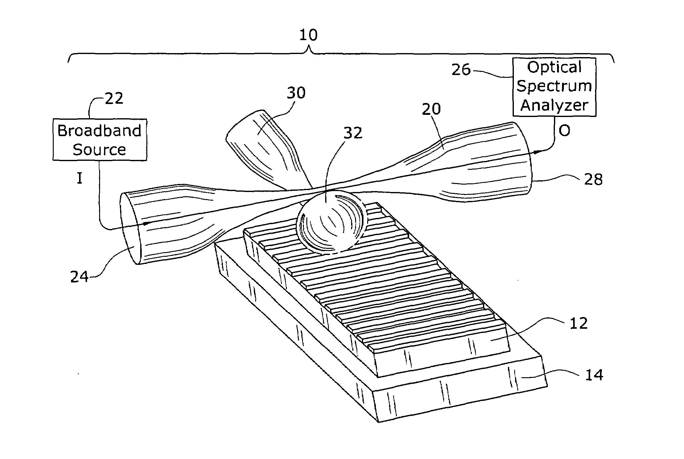
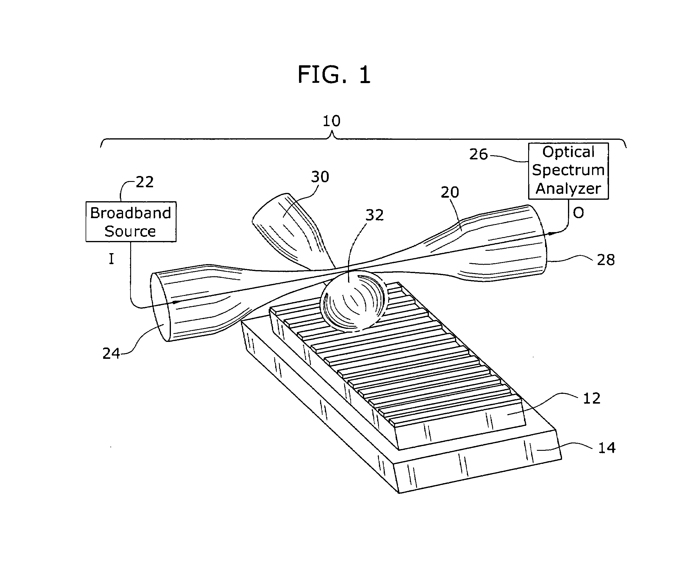
[0015]FIG. 1 illustrates an exemplary microsphere resonant probe 10 formed in accordance with the present invention, as used in this case to assess the surface qualities of an optical phase mask 12. It is to be understood that the use of a phase mask as a “surface under test” is exemplary only; the microsphere resonant probe of the present invention may be used to investigate the surface qualities (i.e., perform optical spectroscopy) of virtually any optical device. In the particular arrangement as illustrated in FIG. 1, optical phase mask 12 is placed upon a translation table 14 which moves in the direction shown to allow for microsphere resonant probe 10 to scan the entire surface of mask 12.

[0016]In accordance with the present invention, microsphere resonant probe 10 comprises a light source for illuminating the surface area, in this particular case using a biconically tapered optical fiber 20, with a broadband light source 22 coupled into a first (input) end 24 of optical fiber ...


PUM


Abstract

An apparatus and method for performing surface microscopy of an optical device uses an optical fiber taper including a microsphere endpoint as a near field probe. A transmission fiber is disposed adjacent to the microsphere so as to evanescently couple an optical test signal into the microsphere. A series of extremely narrow whispering gallery mode (WGM) resonances are created within the microsphere, with an associated electromagnetic field radiating outward therefrom. The microsphere probe may then be moved over the surface of an optical device being analyzed (or the device translated underneath the microsphere), where any abnormalities in the surface (such as defects, scratches and the like) will perturb the electromagnetic field pattern and be reflected in changes in the measured output power from the microsphere.

Description

TECHNICAL FIELD[0001]The present invention relates to a microsphere probe that may be translated across a surface to perform optical surface microscopy and, more particularly, to an optical microsphere resonator probe that performs local surface sensing with whispering gallery mode resonances.BACKGROUND OF THE INVENTION[0002]Whispering gallery modes (WGMs) in optical applications is typically associated with circular-path resonant cavities where light inserted into an optical WGM travels exclusively via total internal reflection, glancing off material interfaces at a near-parallel angle. In recent years, interest in WGM optical resonators has grown dramatically, particularly with respect to its “sensing” applications. Optical sensing generally uses an optical probe beam to interact with a material to be detected. This interaction between the optical probe beam and the material modifies some aspect of the optical probe beam. A portion of this modified beam, such as the scattered ligh...

Claims


Application Information

Patent Timeline
Patent Type & Authority Patents(United States)
IPC IPC(8): G02B6/00G01Q60/18G01Q60/22
CPCG01N21/956G02B6/29341G01N2021/95676G01N2201/08
Inventor SUMETSKY, MIKHAIL
Owner FURAKAWA ELECTRIC NORTH AMERICA INC
Why Eureka
Try Eureka