Apparatus, arrangement and method for braking

a technology of apparatus and braking system, which is applied in the direction of railway braking system, lighting and heating apparatus, furnace components, etc., can solve the problems of not providing the necessary shock absorption, the risk of a queue of pallets being formed before a work station, and the risk of a load being damaged, so as to increase the braking effect, and the braking effect can be varied.

Inactive Publication Date: 2007-05-22
FLEXLINK COMPONENTS
View PDF7 Cites 22 Cited by
  • Summary
  • Abstract
  • Description
  • Claims
  • Application Information

AI Technical Summary

Benefits of technology

[0010]By virtue of providing a braking element which is movable in relation to the matrix, great degrees of freedom for varying the braking effect are obtained in relation to the possibilities which existed in the prior art. The braking effect can be varied considerably by means of different braking-element geometry. In the prior art, on the whole the only feature it is possible to vary in order to vary the braking effect is the nature of the rubber. By virtue of the invention, possibilities have therefore been afforded for significant variations in the braking effect of the braking device. On account of the geometry of the braking element, the braking device can be provided with an increased braking effect when the pallet is driven into from the rear, that is to say in the direction of travel concerned. If the braking element is then designed so that the outer surfaces which are to project through the lateral surface of the braking device are adapted to the curve of the lateral surface, the front part of these will project like barbs and increase the braking effect.
[0011]Another advantage of the device according to the invention is that, in the event of the bearing means forming a queue, it guides each bearing means separately so that they do not skew in the conveying track. This is due to the fact that the braking element projects laterally through the lateral surface of the braking device on both sides transversely to the conveying direction and in this way guides the advance of the bearing means.
[0013]In order to increase the area which can receive pressure in the event of a collision between the bearing means or pallets, that part of the braking element which is arranged so as to project through the lateral surface in the unloaded state can have a crosspiece. In order further to improve the functioning of the braking device, the crosspiece or, if the element does not have a crosspiece, that part of the braking element which projects through the lateral surface in the unloaded state can comprise a stiffening element.

Problems solved by technology

When it is difficult to coordinate the work so that every pallet spends the same length of time in each work station, there is a risk of a queue of pallets being formed before a work station.
If work is being carried out on the load on the pallet in front, there is a risk of the load being damaged.
It has nevertheless been found that this does not provide the necessary shock absorption, for which reason the problem remains to be solved in an effective manner.
However, the construction above affords limited possibilities for varying the braking effect.

Method used


Image

  • Apparatus, arrangement and method for braking
  • Apparatus, arrangement and method for braking
  • Apparatus, arrangement and method for braking

Examples


Embodiment Construction

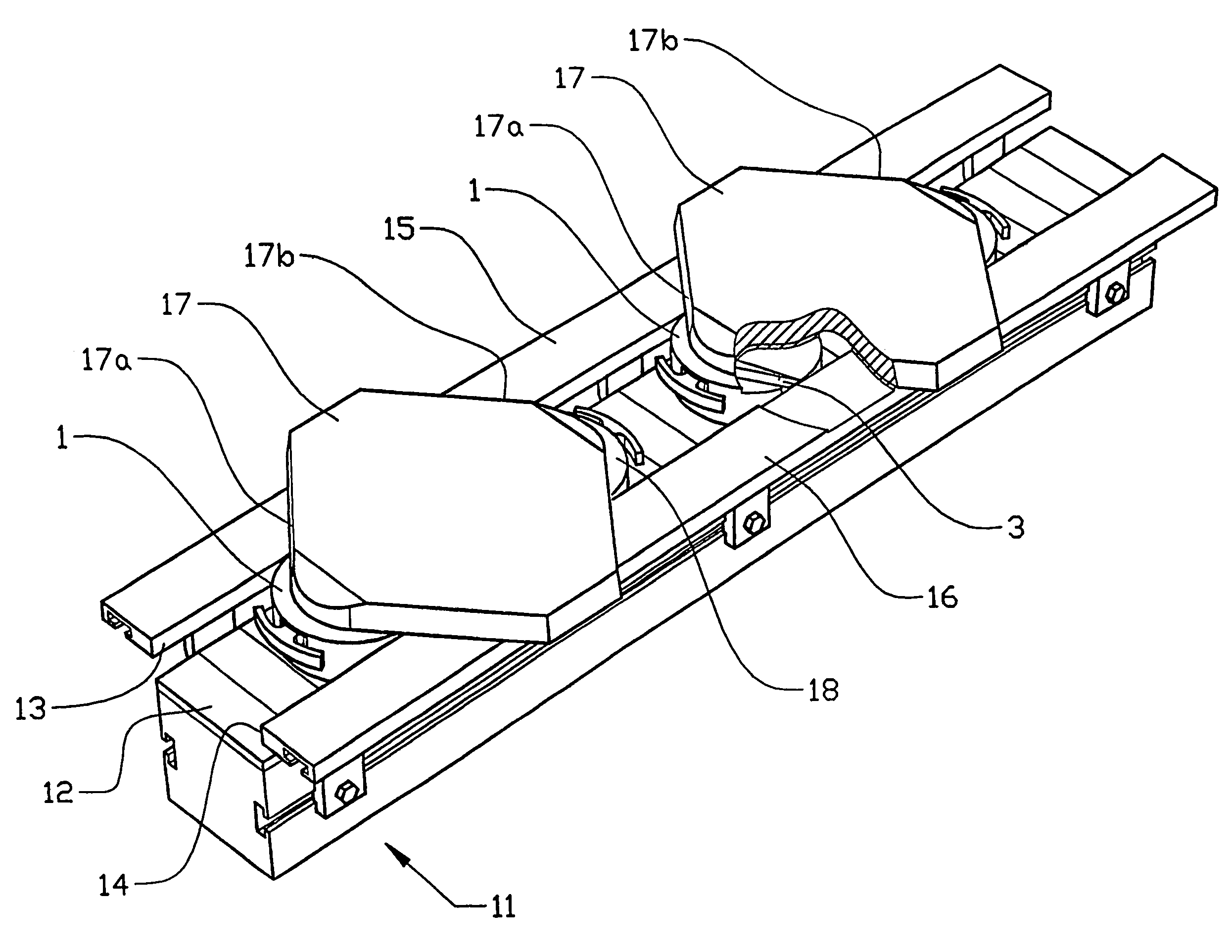
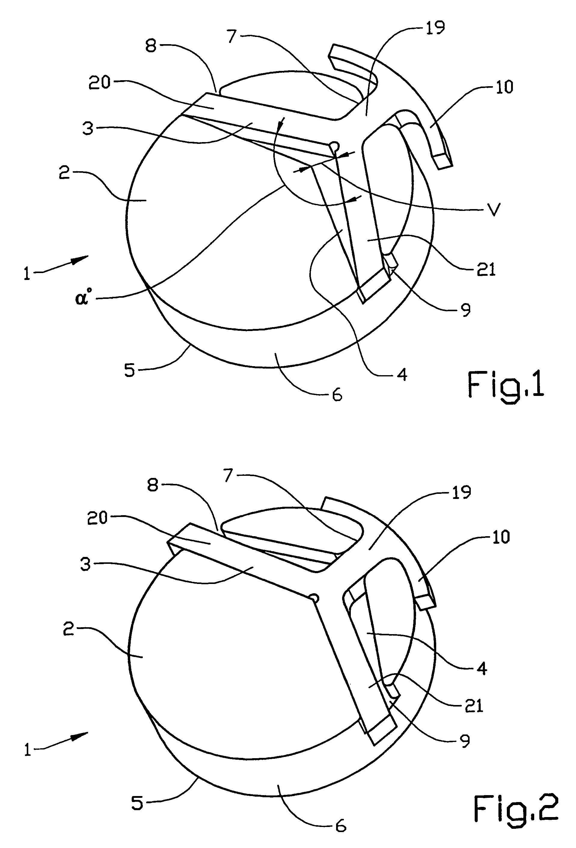
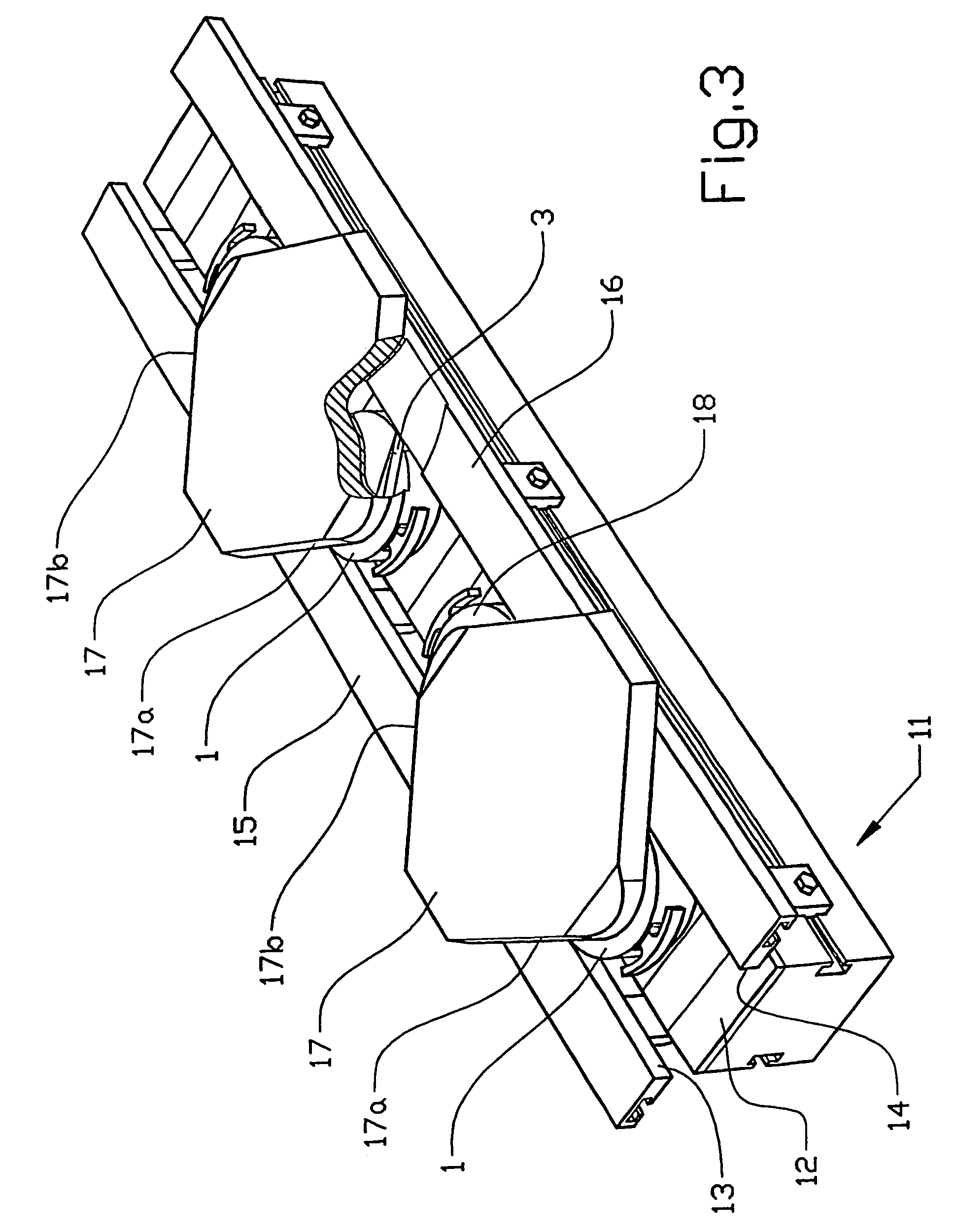
[0025]FIG. 1 shows a braking device 1 according to the invention in the unloaded state. The braking device 1 has an essentially cylindrical shape. Other shapes are also conceivable for the braking device 1. The variations of the geometry are determined by the capacity of the braking device for following a conveying track. The braking device 1 comprises a matrix 2 made of a thermosetting plastic, such as acetal plastic, and a braking element 3 made of rubber, such as polyurethane rubber. The matrix 2 can be made of other relatively rigid materials, such as metal. The braking element 3 is preferably made from rubber, but other elastic materials are also possible. The whole of the braking element 3 does not have to be made from an elastic material. It is possible to envisage arranging stiffening elements made from, for example, metal or thermosetting plastic in the braking element.

[0026]The braking device 1 has a support surface 5 and a lateral surface 6. The braking element 3 is arran...


PUM


Abstract

A braking device for a pallet intended to run in a conveying track. The braking device includes a matrix and a braking element. The matrix includes the support service and exterior surface and a recess having various screws and openings. The braking element includes at least two protrusions which are disposed within the grooves of the matrix and project outwardly from the openings of the matrix at various stages of braking.

Description

TECHNICAL FIELD[0001]The invention relates to a device for braking objects which are conveyed in a track, which device has a lateral surface arranged so as to slide along side surfaces of the track, and at least one support surface arranged so as to slide along a bottom surface of the track. The invention also relates to an arrangement for conveying, which comprises a track having a bottom surface, a first side surface and a second side surface and also at least a first upper surface and a second upper surface, the arrangement comprising at least one bearing means arranged so as to be moved along the upper surface and a braking device which is connected to the bearing means and arranged so as to be moved in the track between the side surfaces, which braking device has at least one lateral surface and at least one support surface. The invention also relates to a method for braking objects which are conveyed along a track comprising a bottom surface, a first side surface and a second ...

Claims


Application Information

Patent Timeline
Patent Type & Authority Patents(United States)
IPC IPC(8): B65G35/08B65G17/00F16D63/00
CPCB65G17/002B65G2201/02
Inventor ROBERTSSON, STAFFANLUMSDEN, THOMASPROGOULAKIS, STAVROS
Owner FLEXLINK COMPONENTS
Why Eureka
Try Eureka