CPP giant magnetoresistive head having antiferromagnetic film disposed in rear of element

a technology of antiferromagnetic film and head, which is applied in the field of cpp (current perpendicular to the plane) giant magnetoresistive head, can solve the problems of difficult improvement of a change (ra) in magnetoresistance per unit area, deterioration of reliability and high-frequency characteristics of the head, and difficulty in reducing the joule heat generated by passing the sensing current, etc., to suppress an increase in the element temperature and prevent heat generation

Active Publication Date: 2007-05-22
TDK CORPARATION
View PDF26 Cites 50 Cited by
  • Summary
  • Abstract
  • Description
  • Claims
  • Application Information

AI Technical Summary

Benefits of technology

[0058]In the present invention, an antiferromagnetic layer is provided in the rear of a giant magnetoresistive element, for pinning the magnetization direction of a pinned magnetic layer, and thus the antiferromagnetic layer is absent from the flowing path of a sensing current to prevent the heat generation from the antiferromagnetic layer even when the sensing current flows therethrough. Therefore, the Joule heat generated by passing the sensing current is significantly decreased to suppress an increase in the element temperature and improve reliability. Also, an increase in recording density can be promoted with narrowing of the reproduction shield distance.
[0059]Furthermore, in the present invention, at least a portion of the pinned magnetic layer extends to the rear of the giant magnetoresistive element in the height direction, and the antiferromagnetic layer provided in the rear of the giant magnetoresistive element in the height direction is in contact with the upper or lower surface of the extending rear portion of the pinned magnetic layer. Therefore, a wide contact area (an area where an exchange coupling magnetic field occurs) can be secured between the pinned magnetic layer and the antiferromagnetic layer, thereby stably and strongly pinning magnetization of the pinned magnetic layer.
[0060]Furthermore, in the present invention, magnetization pinning of the pinned magnetic layer is strengthened by the inverse magnetostrictive effect, shape anisotropy and the seed effect, and thus magnetization of the pinned magnetic layer is little fluctuated, thereby increasing a change ΔR·A in magnetoresistance per unit area. Even if the direction of a sensing current magnetic field is different from the direction of magnetic moment (synthetic magnetic moment) of the pinned magnetic layer, magnetization of the pinned magnetic layer is not fluctuated by the sensing current magnetic field, thereby increasing the sensing current density and output.
[0061]Furthermore, in the present invention, an insulating antiferromagnetic layer is provided for pinning the magnetization direction of the pinned magnetic layer, and thus the sensing current does not flow into the insulating antiferromagnetic layer, thereby suppressing a current loss and increasing output.

Problems solved by technology

Since the temperature of the whole of the head is increased by the generated heat (Joule heat), the reliability and high-frequency characteristics of the head deteriorate.
Also, the thick antiferromagnetic layer 134 causes a difficulty in decreasing the shield distance between the upper and lower shield layers, thereby causing an disadvantage to increasing the recording density.
However, in order to stabilize magnetization of the pinned magnetic layer 133 without using the antiferromagnetic layer 134, the material used for forming the pinned magnetic layer 133 is greatly limited, and it is thus difficult to improve a change (ΔR·A) in magnetoresistance per unit area.

Method used


Image

  • CPP giant magnetoresistive head having antiferromagnetic film disposed in rear of element
  • CPP giant magnetoresistive head having antiferromagnetic film disposed in rear of element
  • CPP giant magnetoresistive head having antiferromagnetic film disposed in rear of element

Examples


first embodiment

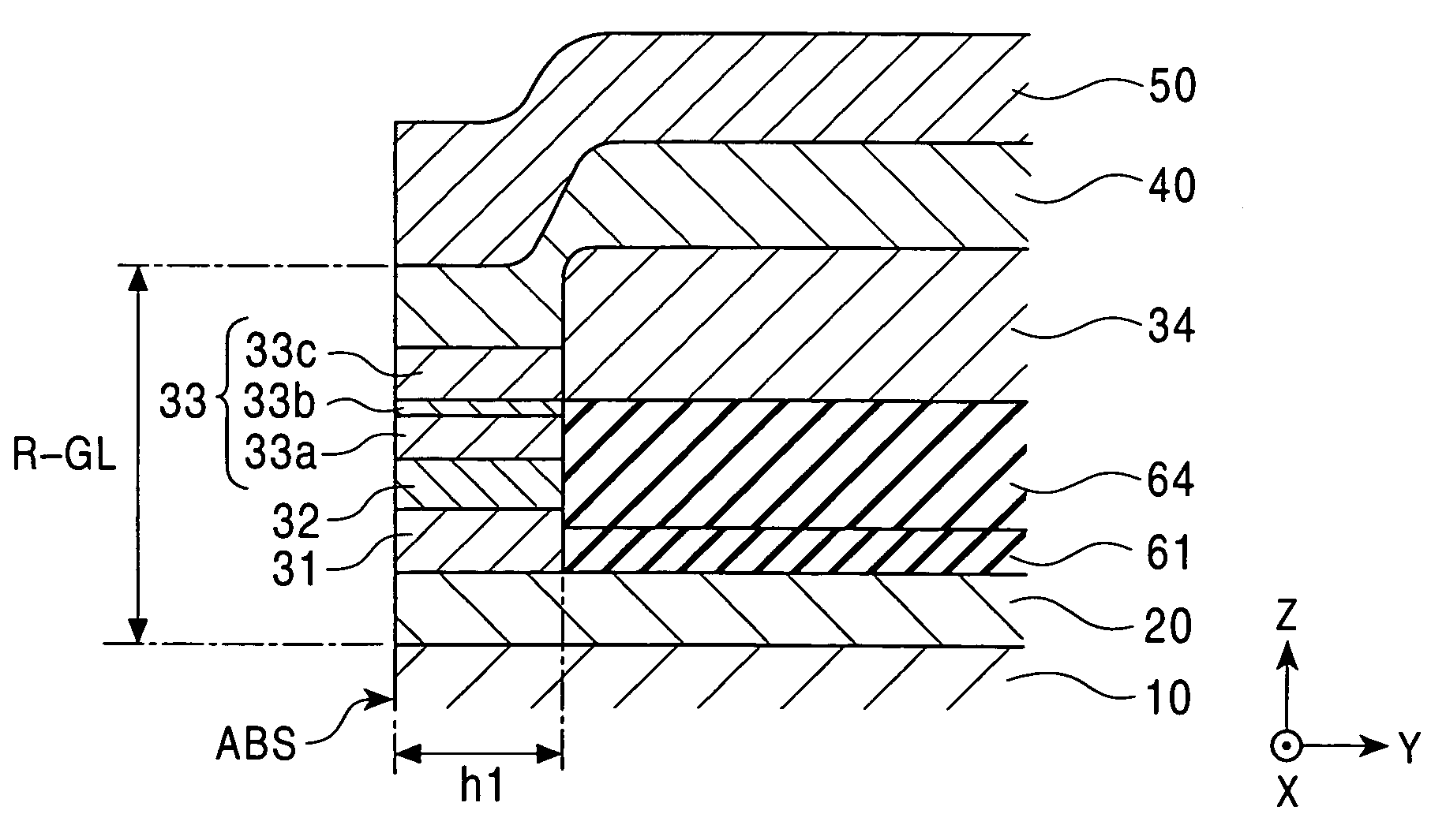
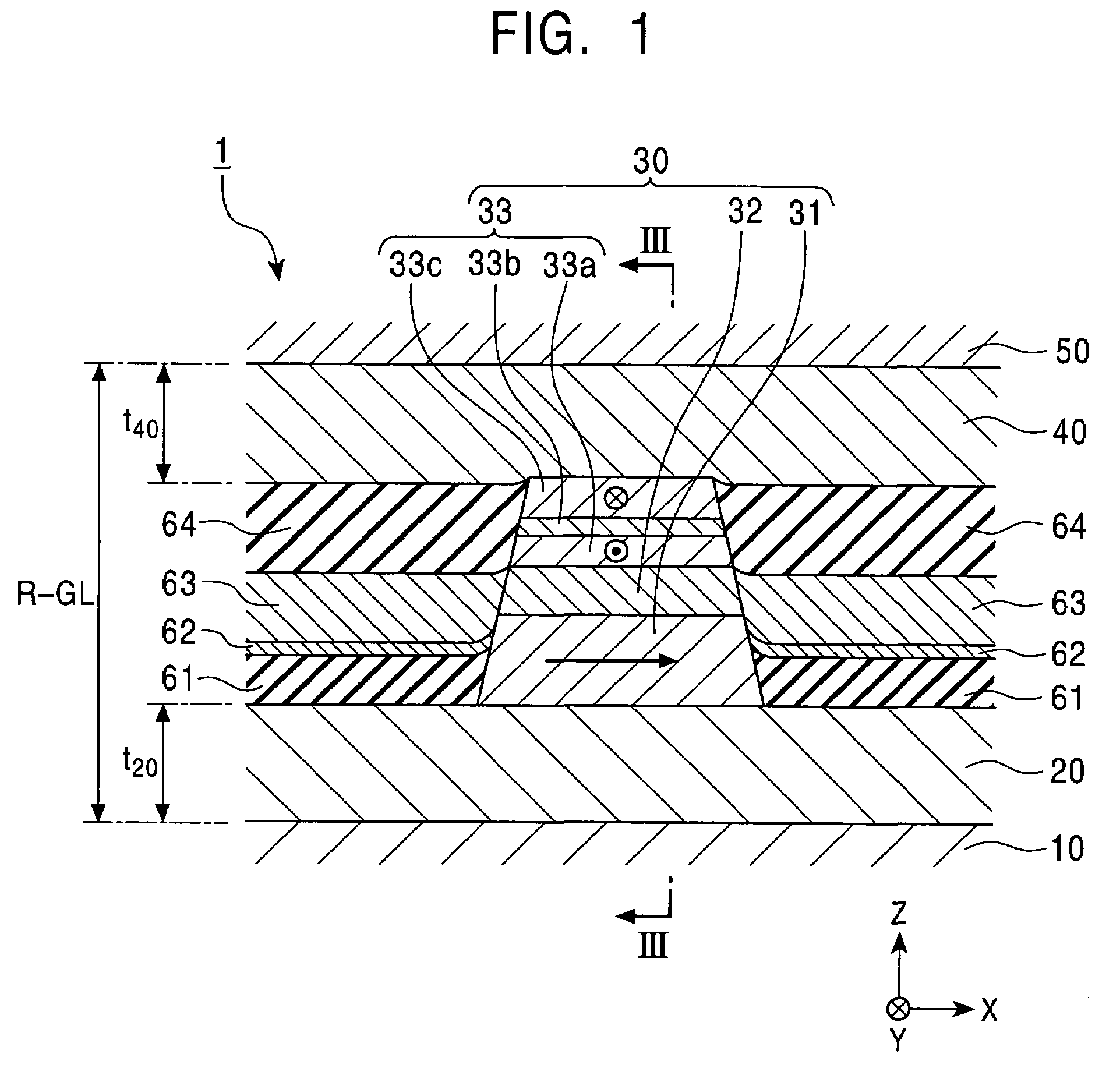
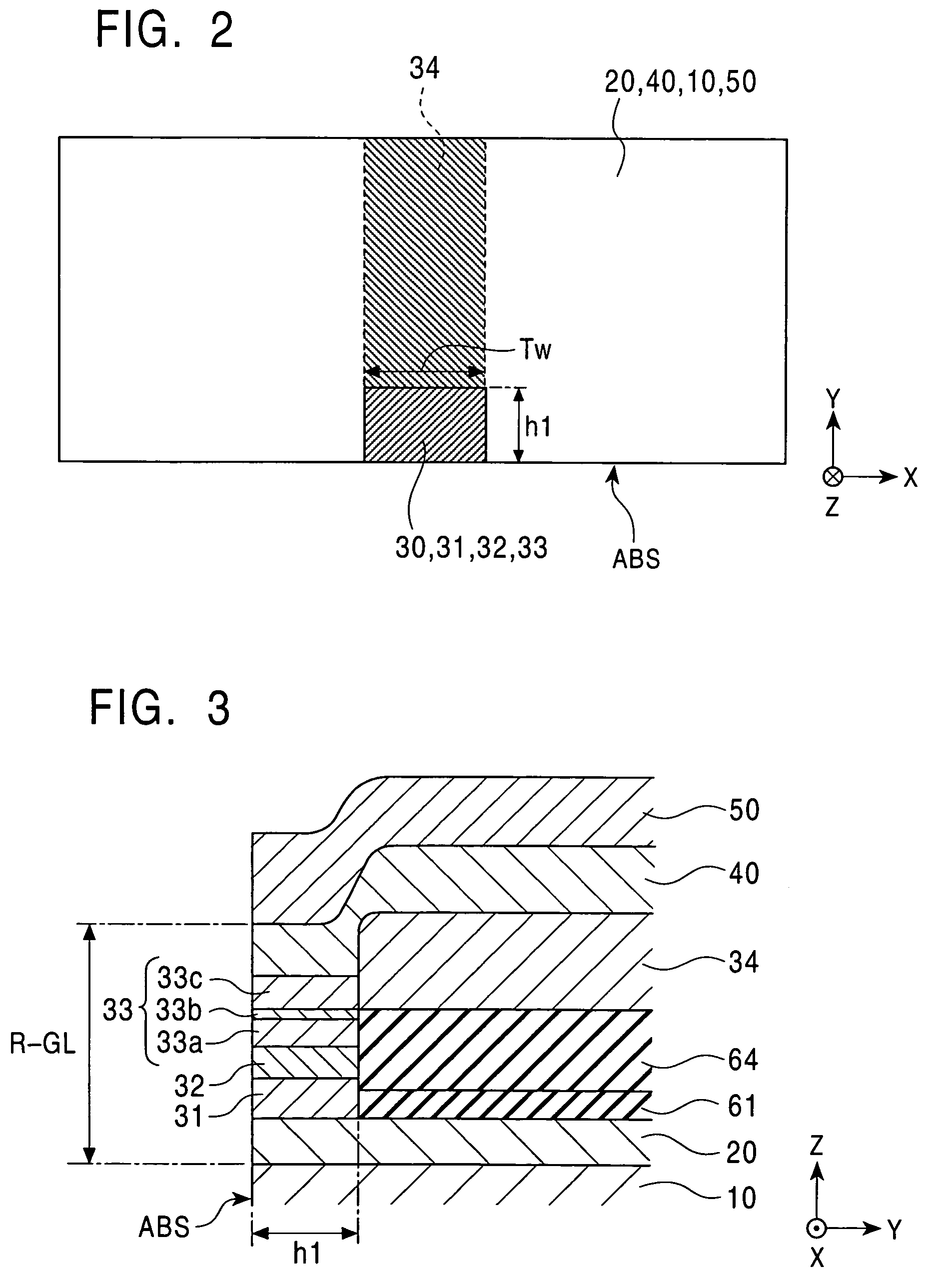
[0118]FIGS. 1 to 5 show a CPP giant magnetoresistive head (CPP-GMR head) according to the present invention. FIG. 1 is a partial sectional view showing the structure of a CPP-GMR head 1, as viewed from a surface facing the recording medium, and FIG. 2 is a schematic top plan view of a GMR element 30, and FIG. 3 is a partial sectional view showing the structure of the CPP-GMR head 1, taken along a central line of the element.

[0119]The CPP-GMR head 1 comprises lower and upper shield layers 10 and 50 with a predetermined shield distance R-GL therebetween in the Z direction shown in the drawing, a lower large-area nonmagnetic metal film 20, the GMR element 30 exhibiting a giant magnetoresistive effect, and an upper large-area nonmagnetic metal film 40, the lower and upper large-area nonmagnetic metal films 20 and 40 and the GMR element 30 being disposed between the lower and upper shield layers 10 and 50.

[0120]Each of the lower and upper shield layers 10 and 50 functions as a magnetic s...

second embodiment

[0152]FIGS. 6 to 13 show a CPP giant magnetoresistive head (CPP-GMR head) according to the present invention.

[0153]The second embodiment is most different from the first embodiment in that the lower and upper large-area nonmagnetic metal films 20 and 40 of the first embodiment are replaced by lower and upper nonmagnetic metal films 220 and 240, respectively, and the antiferromagnetic layer 34 in contact with the rear end surface of the second pinned magnetic layer in the height direction is replaced by an antiferromagnetic layer 234 in contact with the upper surface of a rear portion of a second pinned magnetic layer 231c which extends in the height direction. In the second embodiment, even when the nonmagnetic metal films 220 and 240 are not present in a wide area, the generation of Joule heat can be suppressed because the antiferromagnetic layer 234 is absent from a region where the sensing current flows. Furthermore, a sufficient contact area can be secured between the pinned mag...

third embodiment

[0187]FIGS. 14 to 19 show a CPP giant magnetoresistive head (CPP-GMR heat) according to the present invention.

[0188]The third embodiment is different from the second embodiment in that an antiferromagnetic layer 334 is provided in contact with the lower surface of a first pinned magnetic layer, not the upper surface of a second pinned magnetic layer. The third embodiment is the same as the second embodiment except the arrangement position of the antiferromagnetic layer.

[0189]FIG. 14 is a partial sectional view showing the structure of a CPP-GMR head 301, taken along a central line of an element, FIG. 15 is a partial sectional view showing the structure of the CPP-GMR head 301, as viewed from a surface facing a recording medium, and FIG. 16 is a schematic top plan view of a GMR element 330. In FIGS. 14 to 16, the functions, materials and thicknesses of layers denoted by the same reference numerals as those in the second embodiment shown in FIGS. 6 to 8 are the same as those in the se...


PUM

PropertyMeasurementUnit
resistivityaaaaaaaaaa
thicknessaaaaaaaaaa
thicknessaaaaaaaaaa

Abstract

A CPP giant magnetoresistive head includes lower and upper shield layers with a predetermined distance therebetween, and a giant magnetoresistive element (GMR) including pinned and free magnetic layers disposed between the upper and lower shield layers with a nonmagnetic layer interposed between the pinned and free magnetic layers. A current flows perpendicularly to the film plane of the GMR. The magnetoresistive head further includes an antiferromagnetic layer (an insulating AF of Ni—O or α-Fe2O3) provided in the rear of the GMR in a height direction to make contact with the upper or lower surface of a rear portion of the pinned magnetic layer which extends in the height direction, and an exchange coupling magnetic field is produced at the interface with the upper or lower surface, so that the magnetization direction of the pinned magnetic layer is pinned by the exchange coupling magnetic field in the height direction.

Description

[0001]This application claims the benefit of priority to Japanese Patent Application Nos. 2003-114189, 2003-195159 and 2004-047756, herein incorporated by reference.BACKGROUND OF THE INVENTION[0002]1. Field of the Invention[0003]The present invention relates to a CPP (Current Perpendicular to the Plane) giant magnetoresistive head in which a sensing current flows in the thickness direction (perpendicularly to the film plane).[0004]2. Description of the Related Art[0005]Giant magnetoresistive (GMR) elements used for hard disk devices and magnetic sensors are roughly divided into a CIP (Current in the Plane) type in which a sensing current flows in parallel with the film plane of each of layers constituting an element, and a CPP (Current Perpendicular to the Plane) type in which a sensing current flows perpendicularly to the film plane of each of the layers constituting an element.[0006]FIG. 55 is a longitudinal sectional view showing the structure of a CPP-GMR head using a convention...

Claims


Application Information

Patent Timeline
Patent Type & Authority Patents(United States)
IPC IPC(8): G11B5/127G11B5/39H01L43/08H01L43/10
CPCB82Y10/00B82Y25/00G01R33/093G11B5/3929H01F10/3272H01F10/3218G11B2005/3996Y10T428/1171H01F10/3263Y10T428/1143Y10T428/1121Y10T428/1193
Inventor SAITO, MASAMICHINISHIYAMA, YOSHIHIROIDE, YOSUKEUMETSU, EIJIHASEGAWA, NAOYAHAYAKAWA, YASUO
Owner TDK CORPARATION
Why Eureka
Try Eureka