Electro-luminescence display and drving method thereof

Inactive Publication Date: 2007-05-22
LG DISPLAY CO LTD
View PDF5 Cites 31 Cited by
  • Summary
  • Abstract
  • Description
  • Claims
  • Application Information

AI Technical Summary

Benefits of technology

[0012]The present invention provides an electro-luminescence display which can obtain proper color realization even though identical data driving voltages are applied to each group of R, G, and B pixel cells. This is achieved making a transistor in each driving circuit for an R pixel cell, a G pixel cell, and a B pixel cell to have a different structure, respective

Problems solved by technology

Therefore, the conventional ELD fails to provide proper light realization even when identical driving waveforms are applied to each pixel cell.
In other words, since the brightness according to a current flowing in each EL material composing the EL diode is different, a brightness requi

Method used


Image

  • Electro-luminescence display and drving method thereof
  • Electro-luminescence display and drving method thereof
  • Electro-luminescence display and drving method thereof

Examples


Example

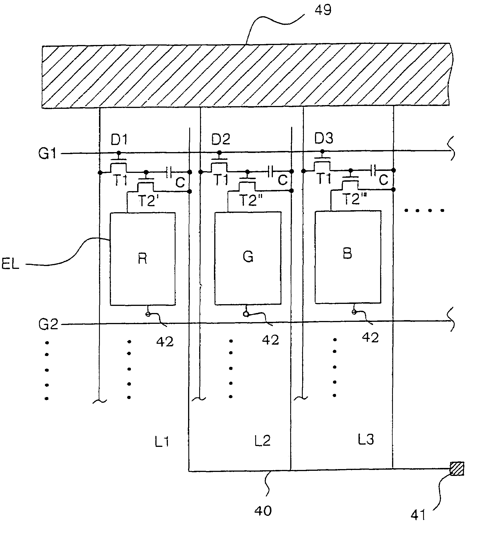
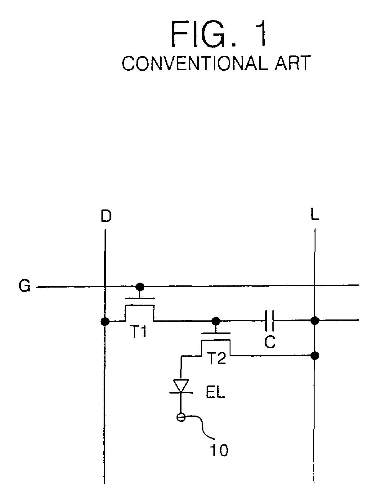
[0018]Referring to FIG. 4, there is shown an electro-luminescence display (ELD) according to an embodiment of the present invention. The ELD has a substrate on which pixel cells emitting red (R), green (G) and blue (B) lights are arranged. The basic elements of each pixel cell, with the exception of the driving devices (transistors) are identical to those in FIG. 1 as described above, and thus an explanation as to the same parts will be omitted.

[0019]In FIG. 4, a number of gate lines G1, G2, etc. cross a number of data lines D1, D2, D3, etc. to define a number of pixel cell areas. At each pixel cell area, power supply lines L1, L2, L3, etc. are arranged in parallel to the data line D1, D2, D3, etc. The power supply lines L1, L2, L3, etc. may be arranged in parallel to the gate lines gate lines G1, G2, etc. Each pixel cell area is provided with a switching device T1, driving device T2′, T2″, T2′″, a storage capacitor C and an EL diode EL. Each pixel cell can be defined as an “R” pixe...


PUM


Abstract

An electro-luminescence display which obtains proper color realization even though identical data driving waveforms are applied to each group of R, G and B pixel cells. In the display, a plurality of data lines cross a plurality of gate lines to define a plurality of pixel cell areas. A plurality of power supply lines pass through the pixel cell areas. A switching device is provided in each pixel cell area in such a manner to be electrically connected to the gate line and the data line. A plurality of driving devices are patterned based on a ratio of channel width to channel length in accordance with the type of pixel cell area. Each driving device having a gate connected to one electrode of the switching device and a source connected to the power supply line at each of the pixel cell areas. A plurality of EL diodes are connected to the plurality of driving devices, respectively. A wiring is commonly connected to the plurality of power supply lines. The R, G and B pixel cells are independently driven using different currents, although a common voltage is received by the driving devices.

Description

BACKGROUND OF THE INVENTION[0001]1. Field of the Invention[0002]This invention relates to an electro-luminescence display (ELD), and more particularly to an active matrix ELD and a method of driving the same.[0003]2. Description of the Related Art[0004]The ELD is a display device in which electrons and holes are injected from the exterior thereof to re-combine the electrons with the holes and thus produce excited molecules so as to exploit the luminescence of these excited molecules. ELD devices are gaining popularity, due to their thin display panel size and relatively low power consumption, because ELDs do not require a backlight device.[0005]FIG. 1 is an equivalent circuit diagram of a unit cell in the conventional ELD. In FIG. 1, a plurality of gate lines G cross a plurality of data lines D to define pixel cell areas therebetween. In the pixel cell area, a power supply line L is arranged in parallel to the data line D. Alternatively, the power supply line L may be arranged in pa...

Claims


Application Information

Patent Timeline
IPC IPC(8): G09G3/30G09G3/32H01L27/12H01L27/32H05B44/00
CPCG09G3/3233H01L27/3211H05B33/08G09G2300/0842G09G2320/0242H01L27/12H01L27/3244Y02B20/325Y02B20/30H05B44/00H10K59/35H10K59/12H01L27/1214
Inventor CHOI, WOONG SIKHAN, CHANG WOOKBAE, SUNG JOON
Owner LG DISPLAY CO LTD
Why Eureka
Try Eureka