Driving circuit of liquid crystal display device
- Summary
- Abstract
- Description
- Claims
- Application Information
AI Technical Summary
Benefits of technology
Problems solved by technology
Method used
Image


Examples
Embodiment Construction
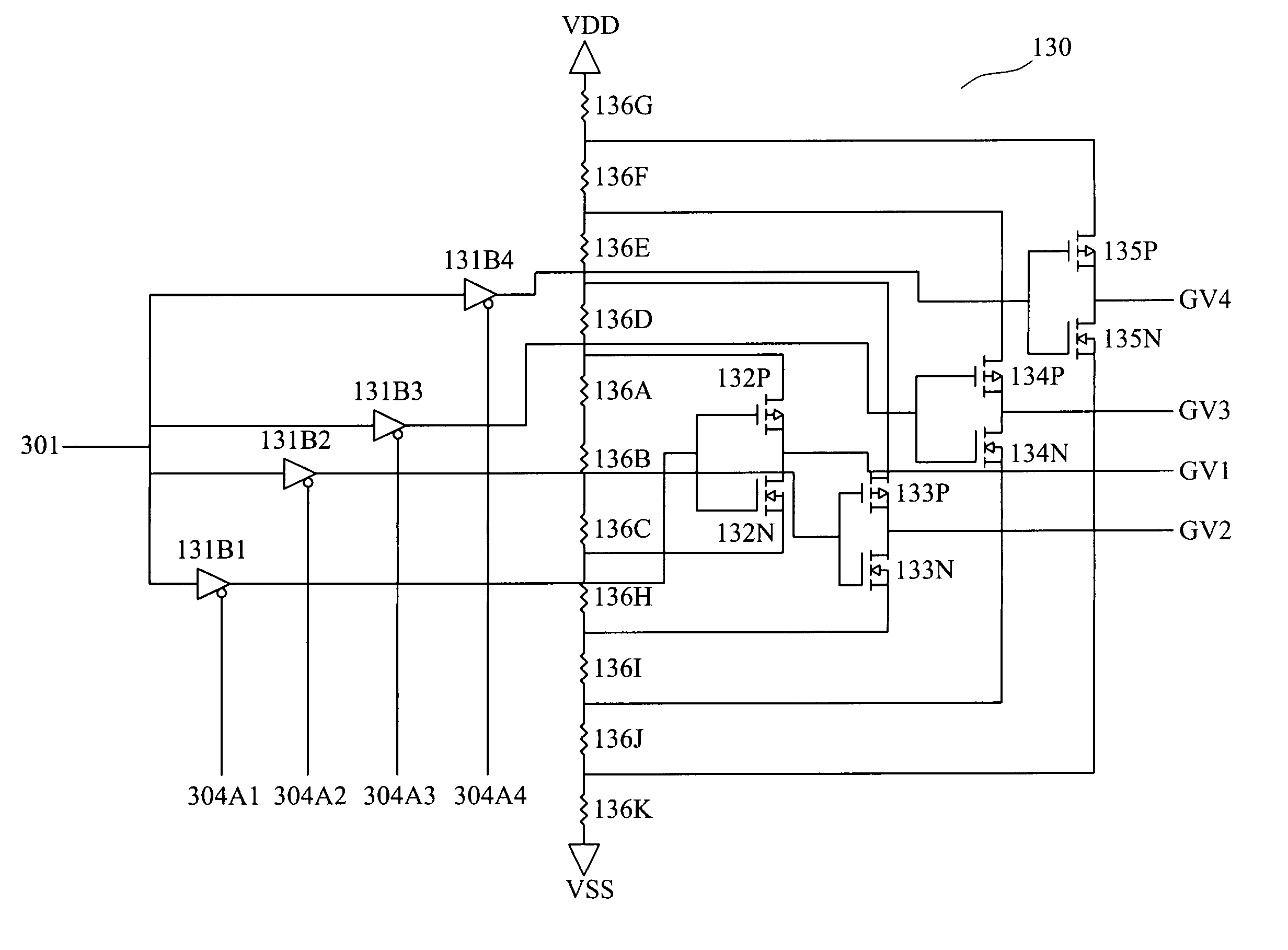
[0017]FIG. 2 is a block diagram of a driving circuit used in a liquid crystal display device according to one embodiment of the invention. A driving circuit 100 used in the liquid crystal display device includes a timing controller 110, a source driver 120 and a low color scale driving circuit 130. The timing controller 110 receives an image data and outputs a digital image signal 302. The timing controller 110 further outputs a polarity-inverting signal 301. The source driver 120 receives a digital image signal 302 and generates an analog image signal 303. The low color scale driving circuit 130 delivers an analog signal 305 in response to the polarity-inverting signal 301 and a first digital signal 304A1, a second digital signal 304A2, a third digital signal 304A3 and a fourth digital signal 304A4.
[0018]FIG. 3 illustrates a block diagram of the source driver 120. The source driver 120 includes a first register 121, a second register 122, a digital / analog (D / A) converter 123, and a...
PUM
 Abstract
Description
Claims
Application Information