Blower for combustion air

a blower and combustion air technology, applied in the direction of combustion process, air transport, plant protection, etc., can solve the problems of insufficient universality of known devices, inability to accurately determine the viscosity, and inability to achieve optimal setting of oxidising agent/fuel mixture, etc., to achieve efficient manufacturing

Inactive Publication Date: 2007-05-29
EBM PAPST LANDSHUT
View PDF6 Cites 37 Cited by
  • Summary
  • Abstract
  • Description
  • Claims
  • Application Information

AI Technical Summary

Benefits of technology

[0009]A device with such a blower is made available which provides and permanently ensures homogenous low-emission combustion to a full mixing surface burner through the acquisition of the air and gas mass current. By combining the blower with a fuel feeder line for the fuel or the gaseous combustion medium, a compact construction unit is provided which significantly reduces installation work when the furnace is manufactured. By acquiring the mass current of the combustion air and the mass current of the combustion medium directly on the air inlet, one obtains the required actual values for control and regulation without interference so that the regulation of the mixture ratio permits a precise setting and low-emission combustion is provided.
[0010]This is particularly an advantage when the mass current sensor is an electronic air mass current anemometer. Such an anemometer has proven useful for various measuring areas and supplies sufficiently precise signals for the determination of the mass current of a gaseous medium.
[0014]It may be favourable that a further mass current sensor is installed in the area of the additional jet gap which sends appropriate signals to the data processing device. This makes it possible to achieve optimal combustion conditions regardless of the fixed values set on the device for the combustion gas.
[0015]It can also be an advantage that the ring jet arrangement is an integral part of the housing wall on the air inlet of the blower. It is favourable that the ring jet arrangement surrounds or forms a ring around the main current of the combustion air on the air inlet. This arrangement ensures continuous homogeneous suctioning of the measuring air current through the applicable jet gap.
[0017]With an additional design form, it may be favourable that the gas feeder is controlled via a rotary valve / regulator valve that is an integral part of the blower housing. It is advantageous that this rotary valve / regulator valve is designed for the gas feeder on the suction side of the blower. This makes manufacturing efficient.
[0019]It is particularly advantageous when the electronic motor commutation handles the mass current evaluation and regulates both the speed of the blower motor and the gas feeder.

Problems solved by technology

Due to measuring errors when the individual parameters are measured, determination of the viscosity is sometimes inaccurate.
Due to this, the setting of the oxidising agent / fuel mixture is not always optimal.
The known device is not particularly universal since it only optimises the gas / air mixture to a specified value.

Method used


Image

  • Blower for combustion air
  • Blower for combustion air
  • Blower for combustion air

Examples


Embodiment Construction

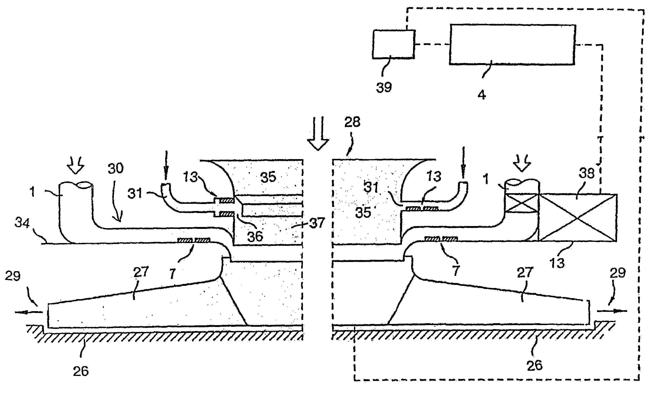
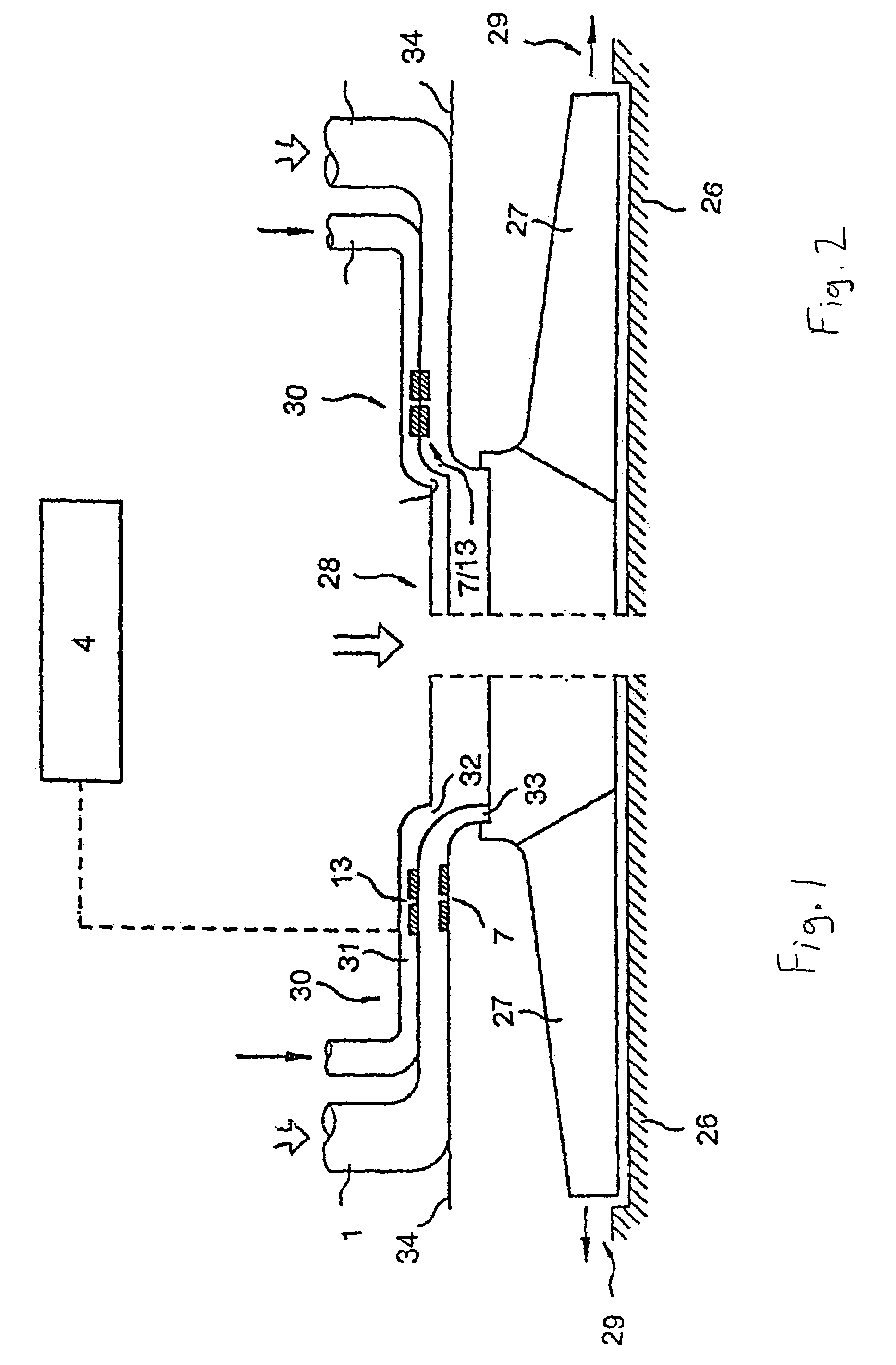
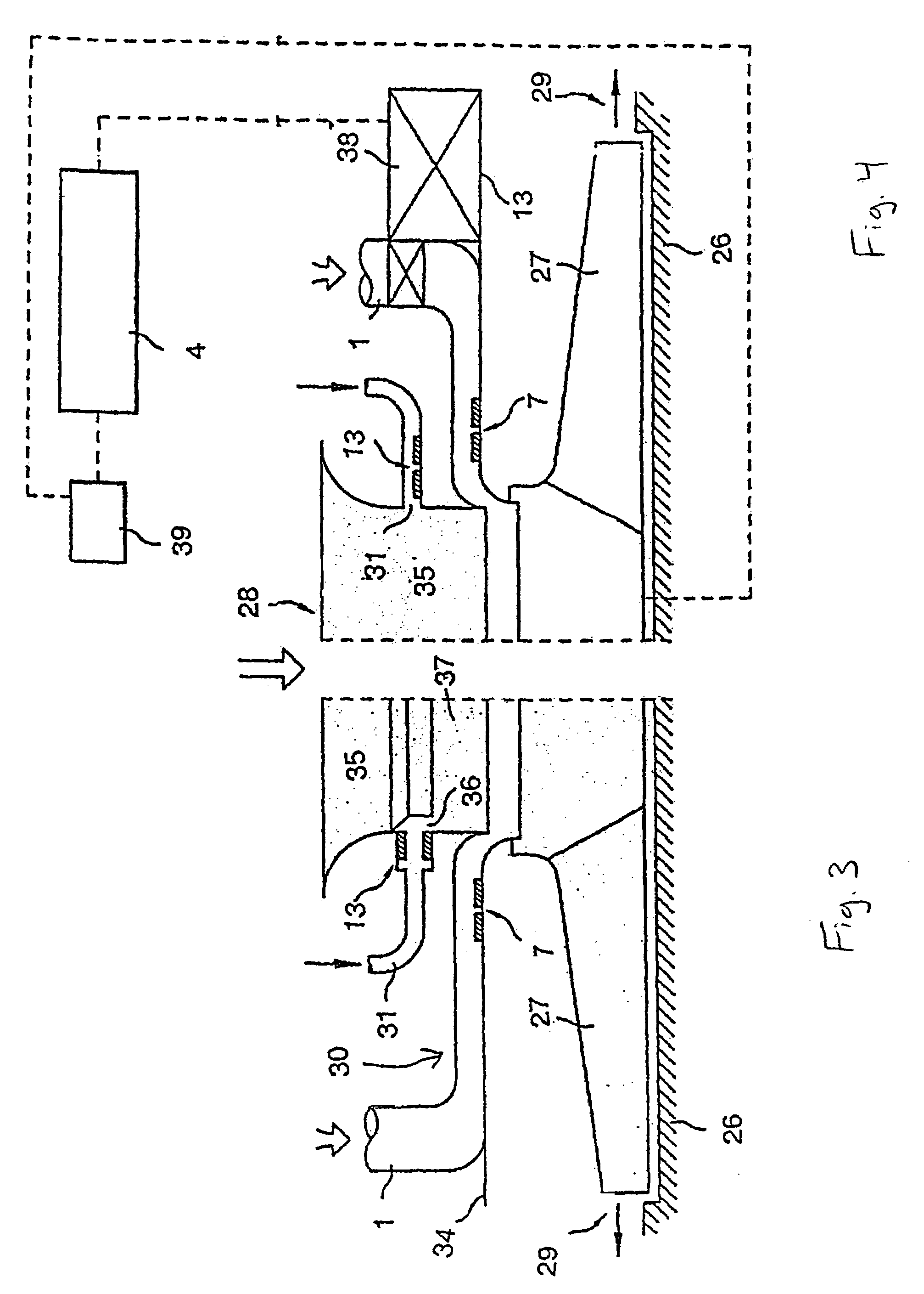
[0026]FIG. 1 shows an example of a blower for combustion air as it is used in so-called wall / floor furnaces. The blower is composed of a fan housing 26 and a fan wheel 27 with an air inlet 28 and an air outlet 29. The air inlet 28 is the suction side of the blower while the air outlet 29 is the pressure side. In the example of the invention shown in FIG. 1, the gas feeder line is again labeled with the reference designation 1. The mass current sensor 13 which is used to determine the air mass current is located on air input 28. The mass current sensor 13 sends signals to a controller-regulator unit or data processing device 4 which controls the combustion, e.g., sets the relationship between combustion medium and combustion air in dependence on the desired heating capacity. The mass current sensor 13 can be an electronic air mass current anemometer as can be procured through conventional sources.

[0027]A ring jet arrangement 30 is located on air inlet 28 wherein the mass current sens...


PUM


Abstract

A blower for combustion air in a wall / floor furnace is provided that includes a blower housing (26), and blower wheel (27), with an air inlet (28) and an air outlet (29), and with a fuel feeder line (1) for fuel, wherein a mass current sensor (13) for determining the air mass current is located on the air inlet (28), which is functionally connected with a data processing device (4) and sends signals to the data processing device for calculation of a ratio of combustion medium to combustion air in dependence on a desired heating capacity.

Description

CROSS REFERENCE TO RELATED APPLICATIONS[0001]This application is a continuation of U.S. patent application Ser. No. 10 / 472,660 filed on Sep. 22, 2003 now U.S. Pat. No. 6,939,127 which is currently pending and is a national stage filing of International Application PCT / EP02 / 03253 filed on Mar. 22, 2002 claiming priority to German patent application 101 12 405.9 filed on Mar. 23, 2001 and German patent application 101 14 901.8 filed on Mar. 26, 2001. The entirety of the disclosure of U.S. patent application Ser. No. 10 / 472,660 is incorporated herein.BACKGROUND OF THE INVENTION[0002]The invention relates to a blower for combustion air.[0003]From DE 29 28 739 B1 a method is known during which a partial current from a combustible gas is taken and is guided over a laminar resistance. The drop in pressure over the laminar resistance is measured at constant temperature or with suitable temperature compensation. The measured pressure drop or the viscosity of the gas can be used to determine ...

Claims


Application Information

Patent Timeline
Patent Type & Authority Patents(United States)
IPC IPC(8): F23N3/00F23N5/18F04D29/42F23D14/60F23N1/02
CPCF04D29/4213F23D14/60F23N1/022F23N5/184F23N2005/181F23N2005/185F23N2021/10F23N2033/08Y02T50/677F04D29/4226F23N2221/10F23N2233/08Y02T50/60
Inventor GOEBEL, PETER
Owner EBM PAPST LANDSHUT
Why Eureka
Try Eureka