Check patentability & draft patents in minutes with Patsnap Eureka AI!

Torque transmission system

Inactive Publication Date: 2007-05-29
DENSO CORP
View PDF6 Cites 2 Cited by
  • Summary
  • Abstract
  • Description
  • Claims
  • Application Information

AI Technical Summary

Benefits of technology

[0009]As a result, the torque fluctuation is sufficiently absorbed. This thereby prevents transmission of a reverse torque to the center hub, loosening of fastening part between the second rotating member and the rotating unit, or abnormal noise or aversive vibration. Furthermore, this enables the elastic coefficients of the first and second torque transmitting members to be relatively small, so that torque fluctuation in a normal or reverse rotation direction can be sufficiently absorbed.

Problems solved by technology

Therefore, in the direct injection type of the internal combustion engine, the torque transmission system disclosed in JP-A-2002-147485 may not sufficiently absorb the torque fluctuation.
When the torque fluctuation is not sufficiently absorbed, various kinds of defects take place.
Namely, a torque limiter wrongly acts, a fastening part between a shaft of a compressor and a hub of the torque transmission system loosens, or abnormal noise or aversive vibration takes place.

Method used


Image

  • Torque transmission system
  • Torque transmission system
  • Torque transmission system

Examples


first embodiment

[0021](First Embodiment)

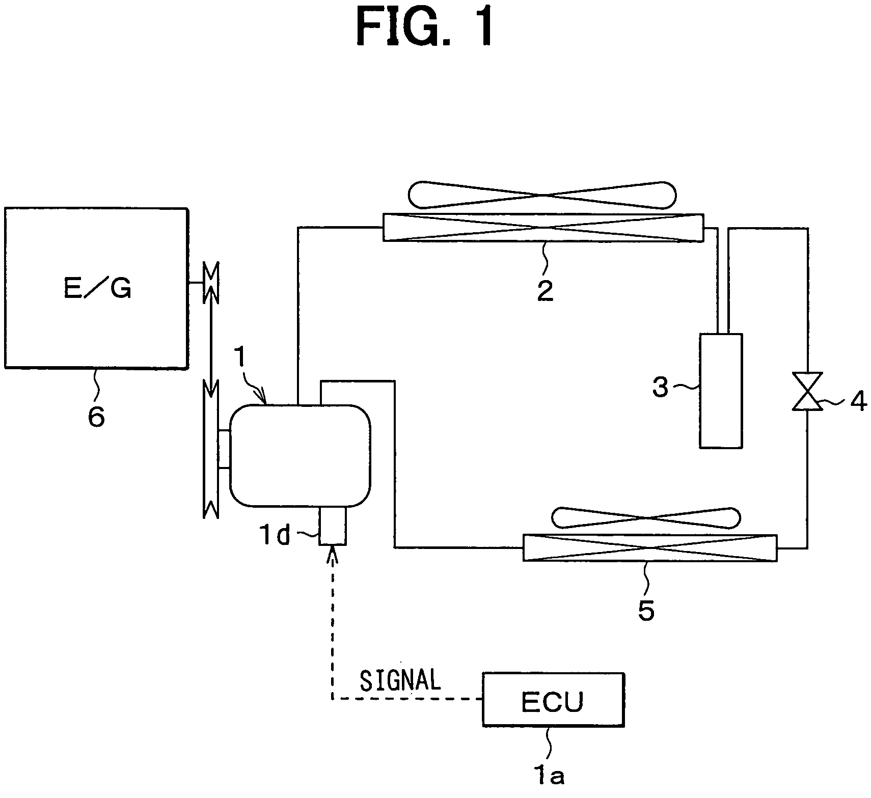
[0022]A first embodiment of the present invention is directed to a torque transmission system that transmits, to a compressor of a vehicular air conditioning system, a driving force of an engine for vehicle traveling. FIG. 1 shows a schematic diagram of the vehicular air conditioning system, i.e., a vapor compression type of a refrigerator.

[0023]A compressor 1 is a variable displacement type that sucks and compresses a refrigerant. A radiator 2 is a high-pressure-side heat exchanger that cools the refrigerant discharged from the compressor 1. A gas-liquid separator 3 is a receiver that separates the refrigerant, flowing out from the heat exchanger 2, into a gas-phase refrigerant and a liquid-phase refrigerant to discharge the liquid-phase refrigerant.

[0024]The compressor 1 changes a discharging amount by changing an inclination angle of a swash plate reciprocating a piston. Here, the discharging amount means a theoretical discharging amount while a shaft is r...

second embodiment

[0048](Second Embodiment)

[0049]In a second embodiment, as shown in FIG. 7, a second damper 14h is provided with a hole portion 14 whose inside distance between facing walls in the rotation direction, i.e., compression direction, can be reduced. The second damper 14h thereby has a non-liner characteristic so that the elastic coefficient of the second damper 14h can be increased with increasing compression transformation. In contrast, a first damper 14g is the same as the first damper 14a in the first embodiment.

third embodiment

[0050](Third Embodiment)

[0051]In a third embodiment, as shown in FIG. 8, both first and second dampers 14i, 14j are provided with hole portions 14o, 14p whose inside distances between facing walls in the rotation direction, i.e., compression direction, can be reduced. The dampers 14i, 14j thereby have non-liner characteristics so that the elastic coefficients of the dampers 14i, 14j can be increased with increasing compression transformation.

[0052]Here, the hole portions 14o, 14p are favorably designed so that the first damper 14i has a greater elastic coefficient than the second damper 14j.


PUM


Abstract

When a first damper contacts both of a protruding portion of a pulley body and a protruding portion of a center hub, a second damper is disposed as being apart from the protruding portion of the center hub with a gap. Even when the pulley body is rotated in a reverse direction, no reverse torque is thereby transmitted to the center hub as long as the gap exists, or before the second damper contacts the protruding portion of the center hub. As a result, torque fluctuation is sufficiently absorbed. This prevents the following: a reverse torque is transmitted to the center hub; a torque limiter wrongly acts; a fastening part between a shaft and the center hub loosens; or abnormal noise or aversive vibration takes place.

Description

CROSS REFERENCE TO RELATED APPLICATIONS[0001]This application is based on and incorporates herein by reference Japanese Patent Application No. 2002-310817 filed on Oct. 25, 2002.FIELD OF THE INVENTION[0002]The present invention relates to a torque transmission system that transmits torque generated by a driving unit to a rotating unit. The present invention is suitably applied to a torque transmission system transmitting a torque from a driving unit such as an engine to a rotating unit such as an alternator or a compressor mounted in a vehicle.BACKGROUND OF THE INVENTION[0003]For instance, as disclosed in JP-A-2002-147485, torque fluctuation in a torque transmission system is conventionally absorbed by using a damper that is formed of elastic material such as rubber when a torque is transmitted from a driving-side rotating unit to a driven-side rotating unit. Here, in the damper disclosed in JP-A-2002-147485, an elastic coefficient k1 in a portion on which a torque acts in a normal ...

Claims


Application Information

Patent Timeline
IPC IPC(8): F16D3/70F16D3/02F16H55/36F16D3/56F16D3/68F16D9/06F16D9/08F16F15/124F16F15/136F16H35/10F16H55/14
CPCF16D3/02F16D3/68F16D9/06F16F15/124F16H55/14F16H55/36F16H2055/366
Inventor NOSAKA, MICHIYASUKUROHATA, KIYOSHI
Owner DENSO CORP
Features
  • R&D
  • Intellectual Property
  • Life Sciences
  • Materials
  • Tech Scout
  • Unparalleled Data Quality
  • Higher Quality Content
  • 60% Fewer Hallucinations
Learn More