Diffraction-based diagnostic devices

a diagnostic device and diffraction technology, applied in the direction of optical radiation measurement, railway signalling, positive displacement liquid engine, etc., can solve the problems of complex visualization device, high cost of prior systems and devices, and inability to view diffraction patterns

Inactive Publication Date: 2007-05-29
KIMBERLY-CLARK WORLDWIDE INC
View PDF210 Cites 41 Cited by
  • Summary
  • Abstract
  • Description
  • Claims
  • Application Information

AI Technical Summary

Benefits of technology

[0017]By “diffraction” it is meant the phenomenon, observed when waves are obstructed by obstacles, of the disturbance spreading beyond the limits of the geometrical shadow of the object. The effect is marked when the size of the object is of the same order as the wavelength of the waves. In the present invention, the obstacles are analytes (with or without or attached microparticles) and the waves are light waves.
[0018]In another embodiment of the present invention, nutrients for a specific class of microorganisms can be incorporated into the receptive material layer. In this way, very low concentrations of microorganisms can be detected by first contacting the biosensor of the present invention with the nutrients incorporated therein and then incubating the biosensor under conditions appropriate for the growth of the bound microorganism. The microorganism is allowed

Problems solved by technology

Many of the prior systems and devices are, however, relatively expensive and require a trained technician to perform the test.
A drawback to this type of device is, however, the fact that the diffraction pattern is not discernible by the naked eye and, thus, a complex visualization device is needed to view the diffraction pattern.
Also, the device is generally not able to detect smaller analytes that do not produce a noticeable diffraction pattern.
A drawback with the device is, however, the relatively high c

Method used


Image

  • Diffraction-based diagnostic devices
  • Diffraction-based diagnostic devices
  • Diffraction-based diagnostic devices

Examples


example

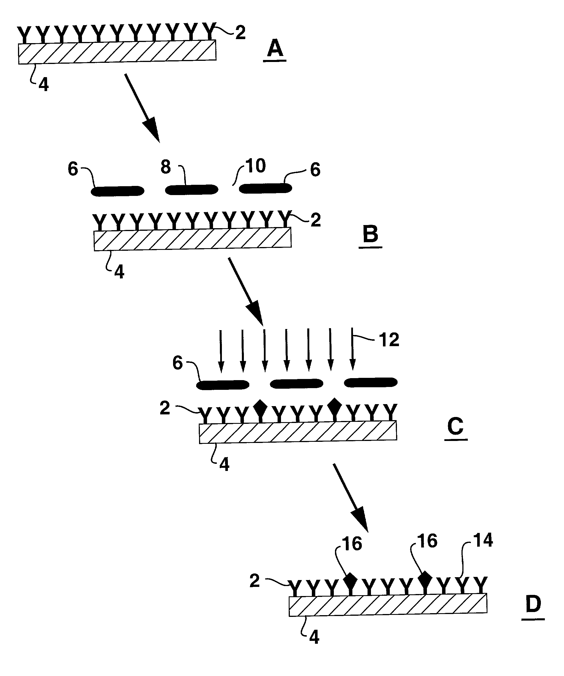
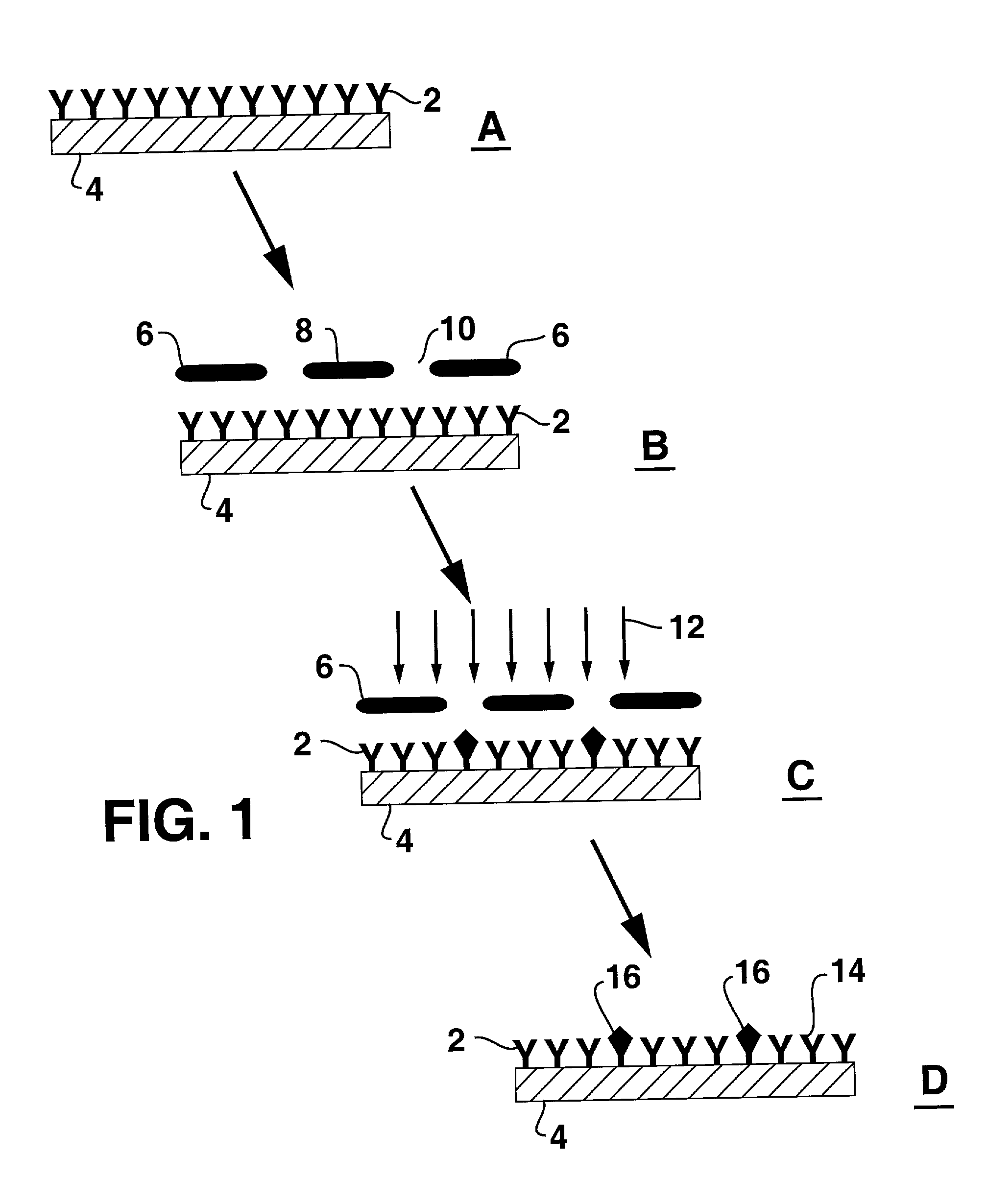
[0048]A 75×50 mm microscope slide (Coming) was coated with polystyrene to serve as a substrate for photopatterning. Initially, the slide was washed with acetone. After drying, the slide was exposed for 1 min to a saturated solution of potassium hydroxide in ethanol. The slide was then rinsed with water followed by ethanol and blown dry with filtered air. The slide was then treated with hexamethyidisilazane for 1 min and spun dry @ 3000 RPM on a spin stand. Finally a 2 percent solution of 280,000 MW polystyrene in toluene was applied to the slide and then spun dry @ 1200 RPM. The polystyrene-coated slide was dipped in a 0.5 mg / ml solution of monoclonal anti-C-reactive protein antibody (Biospacific, #A58040136P, lot# A0640) for 5 min. The slide was then rinsed with 0.2 um filtered water and blown dry with filtered air.

[0049]The antibody layer was photopatterned into inactive and active zones by a 4 min exposure with 222 nanometers light (Heraeus Noblelight, Type VG) through a photomas...


PUM

PropertyMeasurementUnit
Lengthaaaaaaaaaa
Thicknessaaaaaaaaaa
Thicknessaaaaaaaaaa

Abstract

A biosensor includes a substrate with a layer of receptive material disposed thereon. The receptive material is specific for an analyte of interest. A pattern of active and deactivated areas of the receptive material are defined in the receptive material layer by a masking process.

Description

TECHNICAL FIELD OF THE INVENTION[0001]The present invention relates generally to the field of detecting analytes in a medium, and more particularly to a process for preparing analyte-specific diffraction based diagnostic sensors to indicate the presence of the analyte in a medium.BACKGROUND[0002]There are many systems and devices available for detecting a wide variety of analytes in various media. Many of the prior systems and devices are, however, relatively expensive and require a trained technician to perform the test. A need has been recognized in the art for biosensor systems that are easy and inexpensive to manufacture, and capable of reliable and sensitive detection of analytes. Reference is made, for example, to U.S. Pat. Nos. 5,922,550; 6,060,256; and 6,221,579 B1.[0003]Various advances have been made in the industry for producing biosensors. For example, U.S. Pat. No. 5,512,131 to Kumar, et al., describes a device that includes a polymer substrate having a metal coating. A...

Claims


Application Information

Patent Timeline
IPC IPC(8): C12Q1/70C12M1/34C40B40/06C40B40/10C40B60/14G01N33/543
CPCB82Y30/00G01N33/54366G01N33/54373B01J2219/00432Y10S436/805B01J2219/00596B01J2219/00605B01J2219/00612B01J2219/00617B01J2219/00637B01J2219/00659B01J2219/00677B01J2219/00702B01J2219/00722B01J2219/00725B01J2219/0074C40B40/06C40B40/10C40B60/14Y10S435/808Y10S436/811B01J2219/00531G01N33/543C12Q1/00G01N21/47
Inventor KAYLOR, ROSANNCOHEN, DAVIDSAYRE, CURTIS
Owner KIMBERLY-CLARK WORLDWIDE INC
Why Eureka
Try Eureka