

Semiconductor circuit device
a technology of semiconductor circuit devices and circuits, applied in the direction of logic circuit coupling/interface arrangement, power consumption reduction, pulse technique, etc., can solve the problems of reducing the working speed of the circuit, reducing the operating current, and reducing the size of the transistor to control the source node of the transistor driving the signal line, so as to reduce the size of the transistor to control the source node of the transistor. the effect of reducing the size of the transistor
- Summary
- Abstract
- Description
- Claims
- Application Information
AI Technical Summary
Benefits of technology
Problems solved by technology
Method used
Image

Examples
first embodiment
[0059
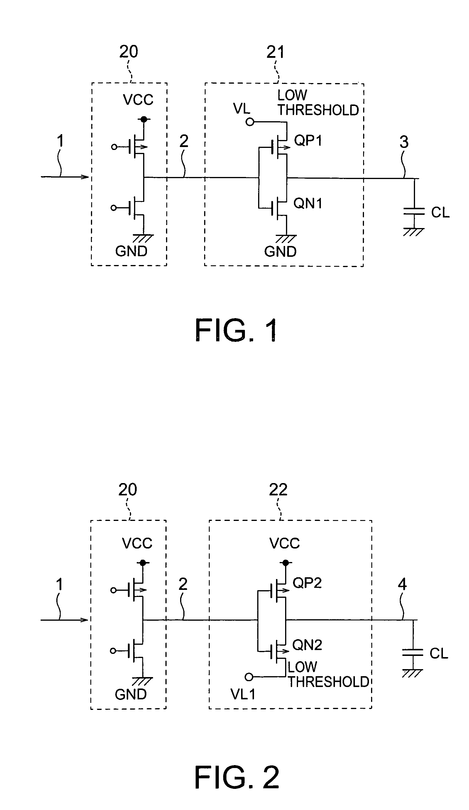
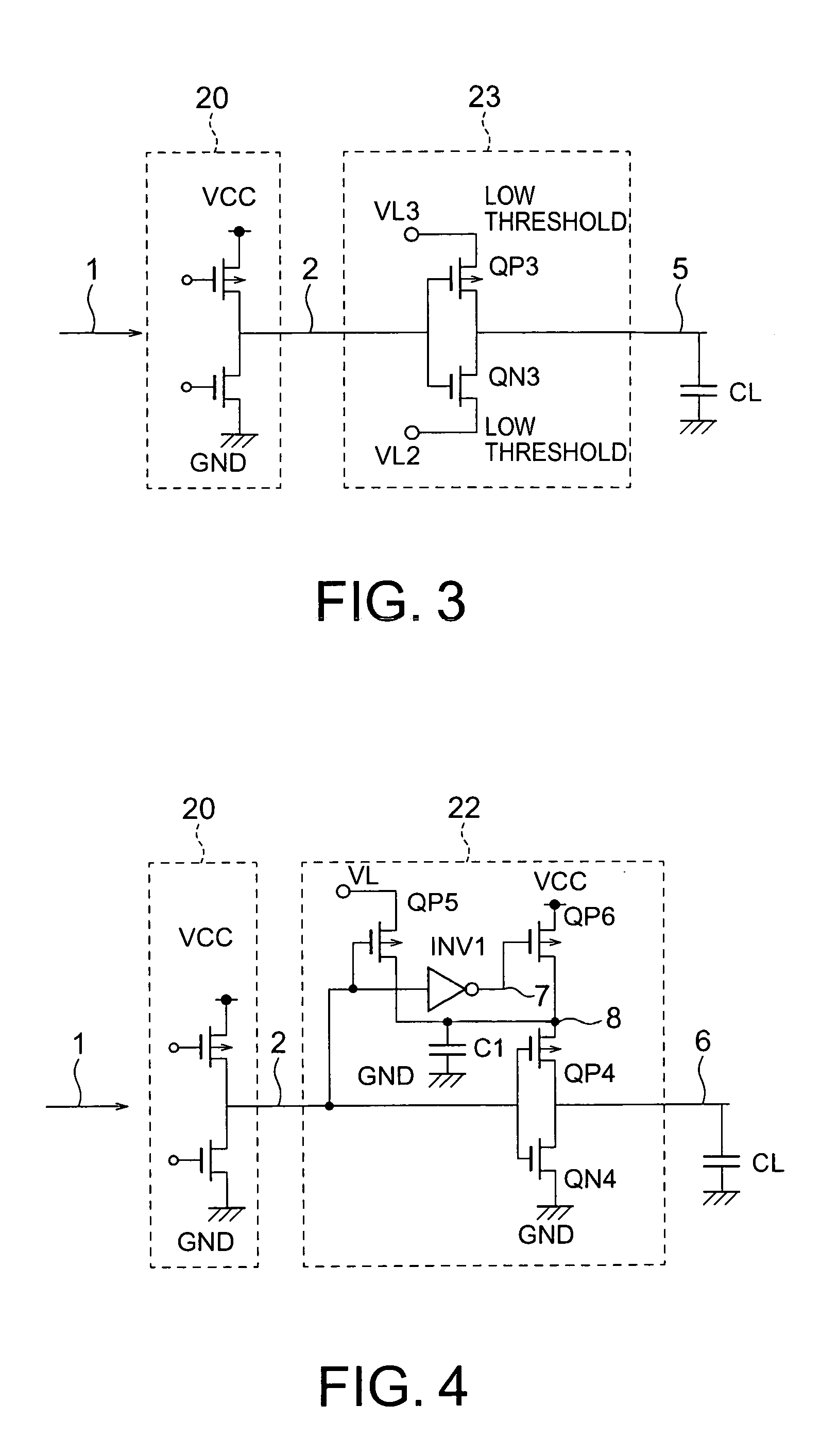
[0060]FIG. 1 shows a circuit block according to a first embodiment of the present invention. The circuit block includes a CMOS circuit including a logic circuit 20 and a signal line driving circuit 21. The logic circuit 20 is arranged between a power supply VCC and ground GND. The logic circuit 20 is a CMOS logic circuit including normal-threshold transistors. The logic circuit 20 performs a logic operation on a signal supplied from an input signal line 1 and generates an output signal in a high level VCC or a low level GND to a node 2.
[0061]The signal line driving circuit 21 is a CMOS inverter including an NMOS transistor QN1 and a PMOS transistor QP1. The source of the NMOS transistor QN1 is connected to the ground as a negative power supply, the gate is connected to the node 2, and the drain is connected to an output signal line 3. The source of the PMOS transistor QP1 is connected to an internal power supply VL as a positive power supply, the gate is connected to the node 2...
second embodiment
[0074
[0075]FIG. 2 is a diagram of a circuit block according to a second embodiment of the present invention. FIG. 6 is a timing chart of the operation according to the second embodiment. A signal line driving circuit 22 according to the second embodiment is an inverter including an NMOS transistor QN2 and a PMOS transistor QP2. The source of the NMOS transistor QN2 is connected to an internal power supply VL1, the gate is connected to a node 2, and the drain is connected to an output signal line 4. The source of the PMOS transistor QP2 is connected to a power supply VCC, the gate is connected to the node 2, and the drain is connected to the output signal line 4. The signal line driving circuit 22 buffers a signal supplied from the node 2 and generates the signal to the output signal line 4. The NMOS transistor QN2 defines a low output level. The PMOS transistor QP2 defines a high output level. A logic circuit 20 is the same as that in FIG. 1. The potential of the internal power supp...
third embodiment
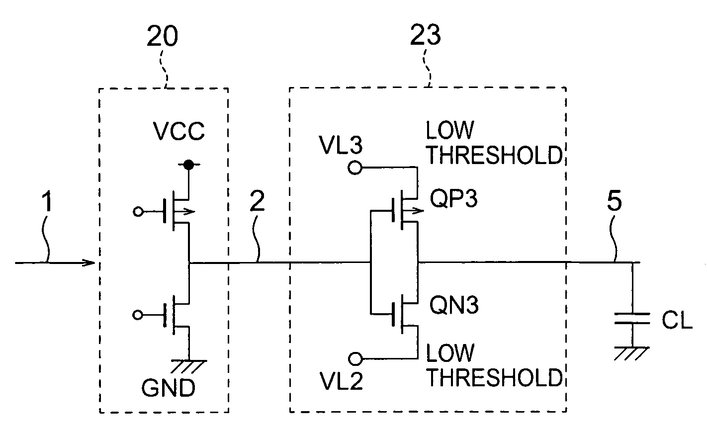
[0080
[0081]FIG. 3 is a diagram of a circuit block according to a third embodiment of the present invention. FIG. 7 is a timing chart of the operation according to the third embodiment. The circuit block according to the third embodiment includes a logic circuit 20 and a signal line driving circuit 23. The signal line driving circuit 23 is an inverter including an NMOS transistor QN3 and a PMOS transistor QP3. The source of the NMOS transistor QN3 is connected to an internal power supply VL2, the gate is connected to a node 2, and the drain is connected to an output signal line 5. The source of the PMOS transistor QP3 is connected to an internal power supply VL3, the gate is connected to the node 2, and the drain is connected to the output signal line 5. The signal line driving circuit 23 buffers a signal supplied from the node 2 and generates the signal to the output signal line 5. The NMOS transistor QN3 defines a low output level and the PMOS transistor QP3 defines a high output l...
PUM
 Abstract
Description
Claims
Application Information