Pseudorandom number generating apparatus or encryption or decryption apparatus using the same

a pseudonym generator and pseudonym sequence technology, applied in the field of pseudonym sequence generation apparatus or pseudonym sequence generation apparatus, can solve the problems of large circuit scale, insufficient processing speed in the case of software implementation, and inability to attempt to use a truly random number sequence. , to achieve the effect of small circuit scale, high processing speed and high security

Active Publication Date: 2007-05-29
HITACHI LTD
View PDF6 Cites 11 Cited by
  • Summary
  • Abstract
  • Description
  • Claims
  • Application Information

AI Technical Summary

Benefits of technology

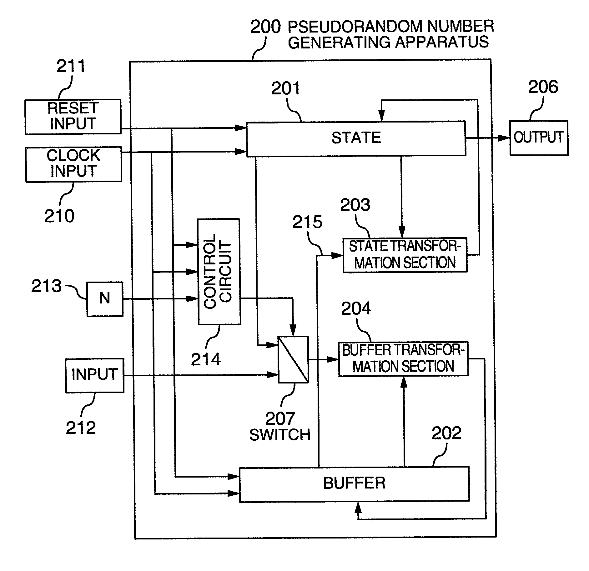
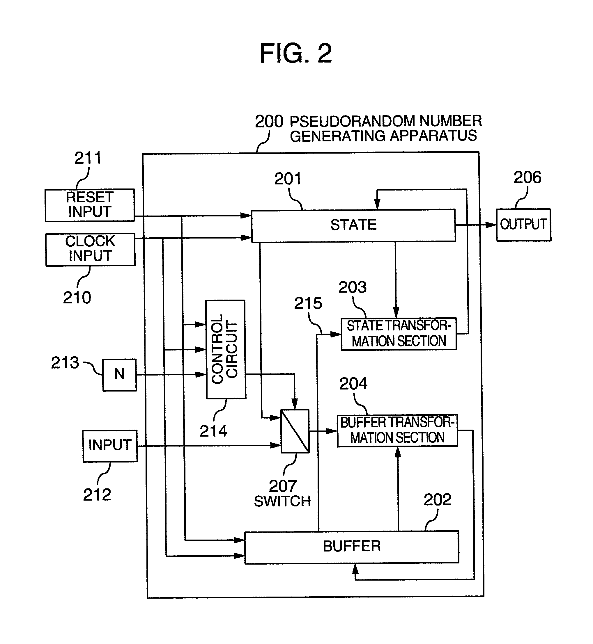
[0009]The present invention provides such a pseudorandom generating method, or apparatus, that the security is high, high speed processing is possible in software as well, and implementation of high speed and small circuit scale is possible in hardware as well.
[0019]In the above-described configuration, parallel processing is made possible by setting the size of the state equal to at least 3 blocks by n bits. In addition, by setting the size of the state equal to 3 blocks by n bits, it becomes possible to make the circuit scale small at the time of hardware implementation. In other words, the above-described configuration makes it possible to implement a pseudorandom number generating apparatus having the following advantages:
[0022](c) the required memory region and the number of gates in hardware implementation are small, and the implementation cost is low.

Problems solved by technology

However, it is impracticable to attempt to use a truly random number sequence in these situations.
For example, in the case of an algorithm especially suitable for software implementation, the circuit scale becomes large because the situation at the time of hardware implementation has not been considered.
However, this is not sufficient in processing speed in the case where software implementation is conducted.
In general, the processing speed is not sufficient as compared with dedicated pseudorandom number generating apparatuses.

Method used


Image

  • Pseudorandom number generating apparatus or encryption or decryption apparatus using the same
  • Pseudorandom number generating apparatus or encryption or decryption apparatus using the same
  • Pseudorandom number generating apparatus or encryption or decryption apparatus using the same

Examples


application example

[0138]One preferred application example of the present embodiment is, for example, a mainstay portion of the network, which needs to conduct an enormous amount of data processing, or a multimedia data processing system, which needs to conduct fast real time processing, Hereafter, data encryption and a discovery system utilizing the present embodiment will be described.

[0139]FIG. 7 is a schematic diagram of a device used in the present embodiment. FIG. 8 shows such an example that a decryption apparatus (904) included in a data transmitter (901) and a data receiver (907) of FIG. 7 is formed by using a pseudorandom number generating apparatus of the present embodiment.

[0140]Data delivery is conducted in the following steps.

[0141]Step 1: A data transmitting person and a data receiving person previously share key information (1001) in secrecy so as to be able to share the same random number sequence. An initial vector or diversification parameter (1002) is also shared although it need n...


PUM


Abstract

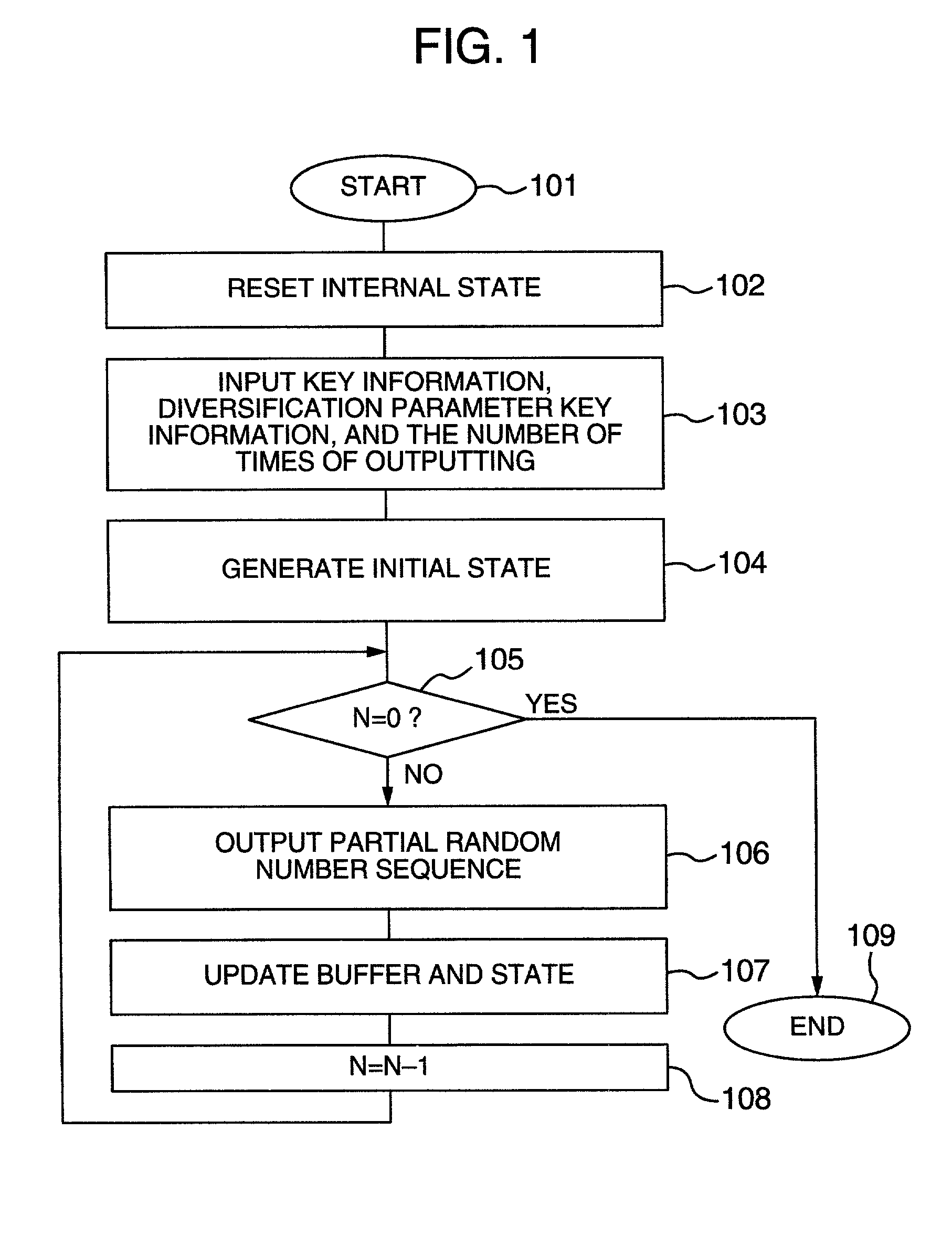
In a buffer and a state included in a pseudorandom number generating apparatus, the state has the configuration of assuming that the unit length of data processing is n, the state has a size of 3×n bits, and the buffer has a capacity of 32×n bits, and according to clock control, a state transformation section (state transformation function) for conducting a state alteration from time t to time t+1 uses a nonlinear function F (having an n-bit input and an n-bit output) twice, or two different nonlinear functions F and G respectively once. The state transformation section has such a configuration that a nonlinear function such as a round function of a block cipher sufficiently evaluated as to the cryptographic security and implementation.

Description

BACKGROUND OF THE INVENTION[0001]The present invention relates to a technique for generating a practical random number sequence and its application technique.[0002]In signature generation utilizing a public key cryptosystem, generation of a key in conducting secret communication, and a stream cipher technique, a random number sequence is highly needed. However, it is impracticable to attempt to use a truly random number sequence in these situations. In practice, there is used a pseudorandom number (hereafter simply referred to as random number) generated by a pseudorandom number generating method or an apparatus using the pseudorandom number generating method. As conditions required of the pseudorandom number as regards use in cryptograph, there are properties concerning the security, such as that the pseudorandom number is unpredictable and the initial value for determining the random number cannot be derived. In addition, in order that the pseudorandom number generating method or ...

Claims


Application Information

Patent Timeline
Patent Type & Authority Patents(United States)
IPC IPC(8): H04L9/00G06F7/58G09C1/00H03K3/84H04L9/22
CPCG06F7/582
Inventor WATANABE, DAIFURUYA, SOICHITAKARAGI, KAZUO
Owner HITACHI LTD
Why Eureka
Try Eureka