Method for determining an optimum gain response in a spatial frequency response correction for a projection system

a spatial frequency response and gain response technology, applied in the field of digital projection device defect correction, can solve the problems of low spatial frequency defect in the resulting image, produced defects in the final image, high spatial frequency defects, etc., and achieve the effect of improving the defect correction and simplifying the defect correction

Active Publication Date: 2007-05-29
IMAX THEATERS INT
View PDF6 Cites 6 Cited by
  • Summary
  • Abstract
  • Description
  • Claims
  • Application Information

AI Technical Summary

Benefits of technology

[0009]It is an advantage of the present invention to provide a non-subjective evaluation of the gain table. The gain at each, or several code values is evaluated statistically from CCD camera data, and not from human judgement. Other means for determining gain at each code value is for subjective human inspection of a projected image, or likewise inspection of prints made from projection onto photographic paper. In the case of photographic paper, the response of the paper, and printing system is not introduced to further complicate judgement of defect correction. This method provides an automated determination of the gain table, which lends itself to a much more timely creation of the gain table.
[0010]In addition to providing better defect correction, the gain table is determined without the full use of a printing system. The printing system will often involve chemicals and tone calibration, as with a traditional photographic printing system. Thus, it is a further advantage of the present invention to allow determination in manufacturing of the correction gain table without full system integration, and use of chemical printing on the assembly line. The correction at this point is independent of paper, and chemistry, and allows for a defect corrected imaging head to be put into any printer with a chemical processor, or sent as field replacement to another processor already in the market. This is not as much of an advantage for imaging heads used in a projection system, however, it still provides for an automated manufacturing approach for digital projection.
[0011]The invention and its objects and advantages will become more apparent in the detailed description of the preferred embodiment presented below.

Problems solved by technology

A problem with all of these devices is that they occasionally produced defects in the final image.
These defects may be due to, for example, surface finishing of the LCD, which results in high spatial frequency defects.
Another defect, again using the LCD as an example, is low spatial frequency defects in the resulting image caused by warping of the support plate as it is attached to the LCD during manufacture.

Method used


Image

  • Method for determining an optimum gain response in a spatial frequency response correction for a projection system
  • Method for determining an optimum gain response in a spatial frequency response correction for a projection system
  • Method for determining an optimum gain response in a spatial frequency response correction for a projection system

Examples


Embodiment Construction

[0025]The present invention will be directed in particular to elements forming part of, or in cooperation more directly with the apparatus in accordance with the present invention. It is to be understood that elements not specifically shown or described may take various forms well known to those skilled in the art.

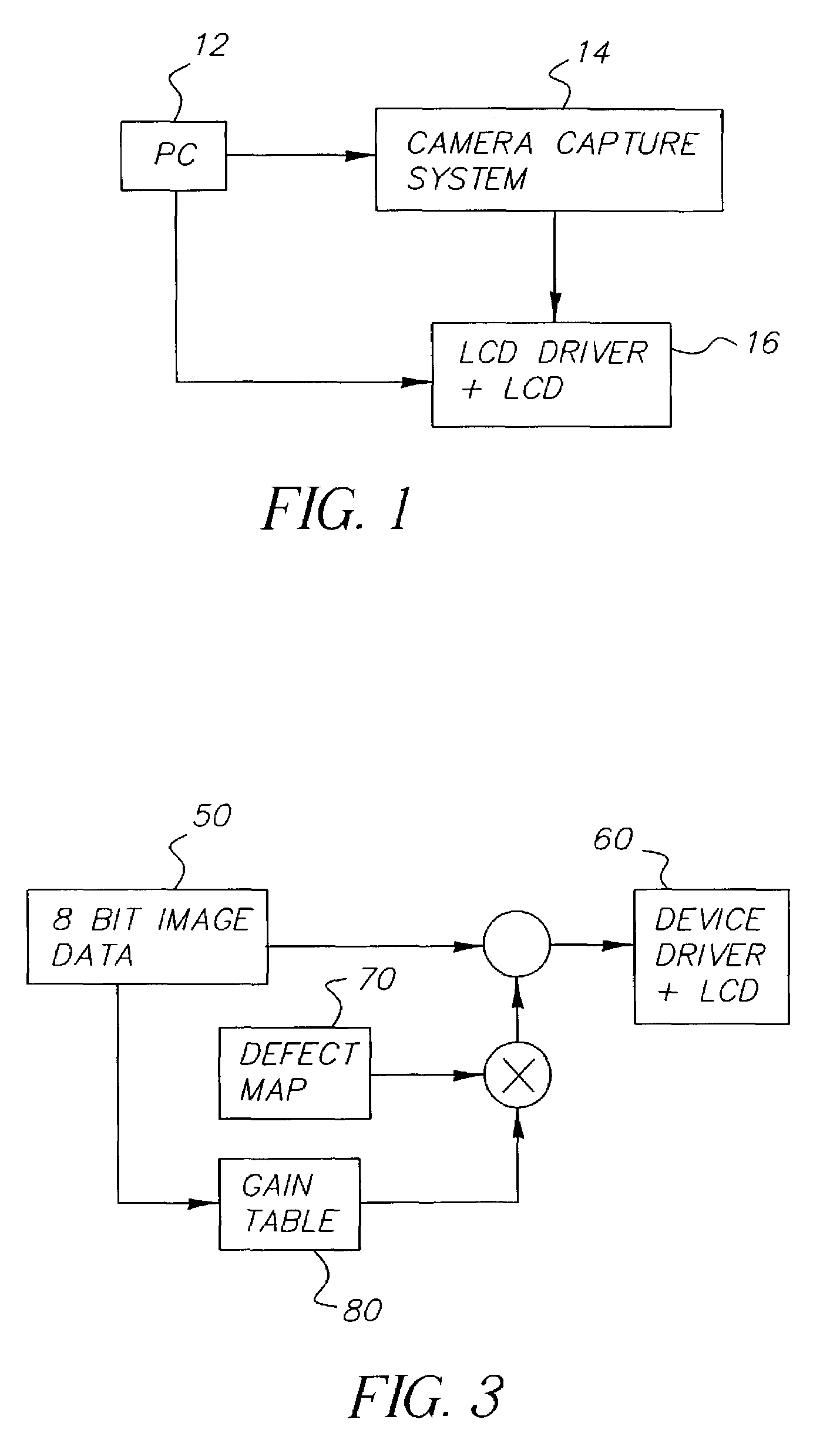
[0026]Referring now to FIG. 1 a personal computer (PC) 12 controls the camera capture system 14, and retrieves images from the camera capture system 14, along with controlling the liquid crystal device (LCD) through it's driver 16. The camera capture system block and LCD driver plus LCD are also shown in FIG. 1. The PC is also used for image processing and determination of the gain table response of the present invention.

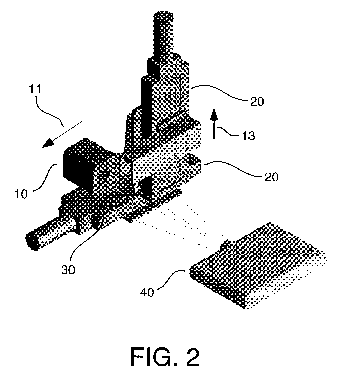
[0027]Referring next to FIG. 2 an assembly drawing shows the camera capture system 14 assembly including a camera 10, translation stages 20, for moving the camera in an x, y plane with respect to the image plane 30 created by LCD driver and projection syst...


PUM


Abstract

A method for determining an optimum gain response in a spatial frequency correction for a projection system comprises the steps of setting a code value (100) to a first code value; projecting a flat field image at the code value; capturing the flat field image (540) with a camera; creating a defect map (70) of defects in the flat field image; applying the defect map to the flat field image to form a corrected image; setting a gain table (80) to a first gain for the corrected image; applying the gain table to the corrected image; registering the corrected image; filtering the registered image; measuring the filtered image for a standard deviation (570); determining whether all gains for producing an under corrected image (60) and an over corrected image have been exhausted for the code value; if all gains have not been exhausted for the code value, set the gain table to the first gain plus n and go to the step of applying the gain table to the corrected image, if all gains have been exhausted go to determining an optimum gain for the code value.

Description

CROSS REFERENCE TO RELATED APPLICATIONS[0001]Reference is made to commonly-assigned U.S. patent application Ser. No. 09 / 606,891, filed Jun. 29, 2000, now U.S. Pat. No. 6,943,919, entitled A METHOD AND APPARATUS FOR CORRECTING DEFECTS IN A SPATIAL LIGHT MODULATOR BASED PRINTING SYSTEM, by William M. Bamick and U.S. patent application Ser. No. 09 / 712,641, filed Nov. 14, 2000, now abandoned, entitled METHOD OF COMBINING ACQUIRED DIGITAL DATA TO CONSTRUCT A COMPOSITE IMAGE, by Jose A. Rosario et al., the disclosures of which are incorporated herein.FIELD OF THE INVENTION[0002]The present invention relates in general to defect correction of digital projection devices and in particular to generating a gain table response for defect correction from scans of images corrected from a composite image defect map.BACKGROUND OF THE INVENTION[0003]Digital printing is often achieved using a single spatial light modulator, such as a low cost liquid crystal display (LCD) modulator, to expose photogra...

Claims


Application Information

Patent Timeline
Patent Type & Authority Patents(United States)
IPC IPC(8): G06K9/40H04N1/407G06T5/00H04N5/74H04N17/00
CPCH04N5/74H04N9/3194
Inventor BERNARDI, BRYAN D.BARNICK, WILLIAM M.TUCKER, DALE L.MUNIZ, DAMIAN M.
Owner IMAX THEATERS INT
Why Eureka
Try Eureka