Radio system

a radio system and radio technology, applied in the field of radio systems, can solve problems such as the inability to determine the absolute position of portable devices

Inactive Publication Date: 2007-05-29
OMRON AUTOMOTIVE ELECTRONICS CO LTD
View PDF21 Cites 73 Cited by
  • Summary
  • Abstract
  • Description
  • Claims
  • Application Information

AI Technical Summary

Benefits of technology

[0014]An object of the present invention is to provide a radio system including a portable device and a stationary device, which can determine a position of the portable device exactly and in finer steps.

Problems solved by technology

Such a radio system, which includes a single antenna corner and determines the position of the portable device in the terms of a distance from the antenna by using the reception intensity data from the antenna, cannot determine an absolute position of the portable device (although it can detect only whether or not the portable device approaches to the antenna).

Method used


Image

  • Radio system
  • Radio system
  • Radio system

Examples


first embodiment

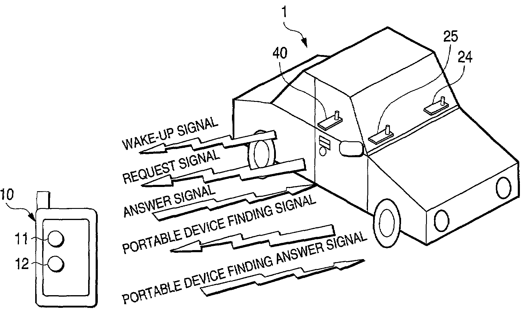
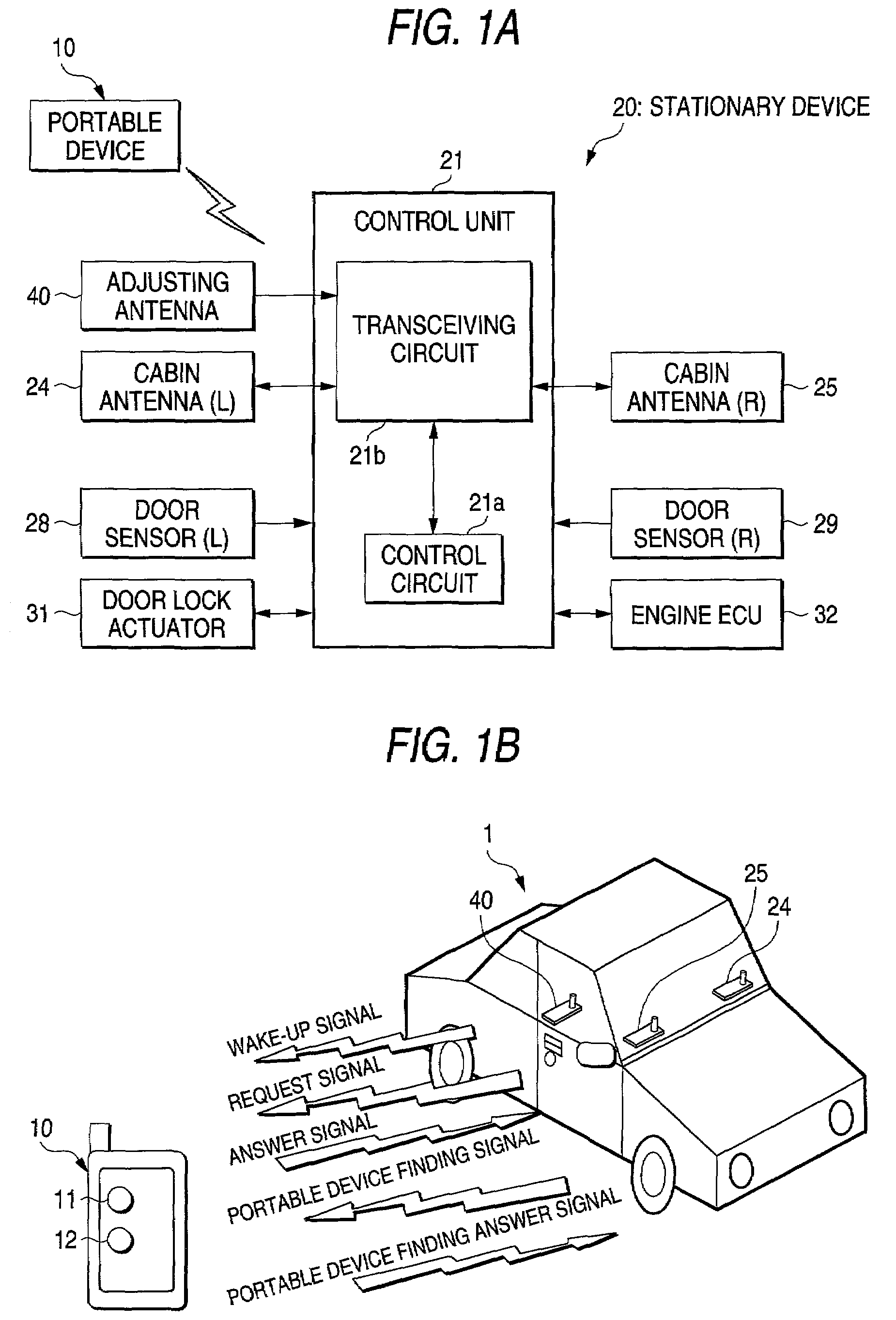
[0054]A first embodiment of the present invention will first be described. In the embodiment, the present invention is applied to a radio system for an entry system and an engine control system (with the immobilizer function) in a motor vehicle 1 of the two door type, as shown in FIG. 1B.

[0055]The radio system, as shown in FIG. 1A, includes a portable device 10, a stationary device 20 mounted on the motor vehicle 1, and an adjusting antenna 40 for adjusting a transmission output power.

[0056]In FIG. 1A, reference numerals 28 and 29 are door sensors for sensing the opening and closing of the right and left doors of the motor vehicle 1. Reference numeral 31 is a door lock actuator as a drive power source for a door lock device of the motor vehicle 1. Reference numeral 32 is a control unit for an engine control system of the motor vehicle 1.

[0057]Those sensors 28 and 29 are used for triggering the position determining process of the portable device and the selecting (adjusting) process ...

second embodiment

[0121]A second embodiment of the invention will be described. In the second embodiment, a part of the FIG. 5 process of the first embodiment is modified.

[0122]In the process of selecting the transmission output power (step S1 in FIG. 5), an output adjustment process as shown in FIG. 6 is executed for each selection, and the transmission output power in the engine start / stop control mode is set (adjusted) to a preferable value for each selection. The transmission output power adjusting technique to be described hereunder may be applied to the adjustment of the transmission output power of the portable-device finding signal (the same thing is true for other embodiments to be described later).

[0123]In this case, the control circuit of the portable device 10 having received the mode select report signal sets a parameter N (integer) used for determining the transmission output power to “1” (step S21). Then, the adjusting transmission output power of the transceiving circuit of the portab...

third embodiment

[0133]Now, a third embodiment of the invention will be described. Also in this embodiment, the FIG. 5 control process in the first embodiment is modified partly.

[0134]In the embodiment, an output power adjusting process shown in FIG. 5 is adjusted every time the output power selection of the step S11 in FIG. 5 is executed. The transmission output power for the engine start / stop control mode is optimized every output power selection.

[0135]In this case, the control circuit of the portable device 10, when receiving the mode select report signal, first sets the parameter N (integer) for determining the transmission output power to “10” (step S31). Thereafter, the transmission output power for adjustment of the transceiving circuit of the portable device 10 is set to “KN” (step S32)

[0136]Then, the control circuit of the portable device 10 sends an adjusting signal of the output power KN (step S33).

[0137]Then, the control circuit judges whether or not the reception ready signal containing...


PUM


Abstract

A stationary device 20 sends a portable-device finding signal to a portable device 10 from a plurality of stationary-device side antennae 24 and 25, which are located at different positions. Upon receipt of the portable-device finding signal from the stationary device 20, the portable device 10 sends a reception intensity data signal to the stationary device 20. The stationary device 20 determines the current position of the portable device 10 by using reception intensity data of the portable-device finding signals, which are received at the stationary-device side antennae, from the portable device 10.

Description

CROSS-REFERENCE TO RELATED PATENT APPLICATIONS[0001]Japan Priority Application 2000-260658, filed Aug. 30, 2000 including the specification, drawings, claims and abstract, is incorporated herein by reference in its entirety.BACKGROUND OF THE INVENTION[0002]1. Field of the Invention[0003]The present invention relates to a radio system, which enables operations of an entry system, an engine control system and the like for the vehicle (e.g., unlocking operation of the doors, and permission of engine start) to be performed without bothersome operations by the user.[0004]2. Description of the Related Art[0005]An example of a system including this type of radio system is a smart entry system for use with a vehicle, recently emerged in the market. This system is developed from the keyless entry system, and is also called a passive or hands free entry system. This system includes a portable device that may be carried by a user, and a stationary device (in this case, it is a device mounted o...

Claims


Application Information

Patent Timeline
Patent Type & Authority Patents(United States)
IPC IPC(8): H04Q7/20B60R25/01B60R25/04B60R25/24B60R25/30F02D45/00F02P11/04G07C9/00H04B1/3822H04B1/40H04Q9/00H04W4/04H04W64/00H04W92/08H04W92/10
CPCB60R25/24G07C9/00309G07C2009/00793G07C2209/63
Inventor HARA, KENTARO
Owner OMRON AUTOMOTIVE ELECTRONICS CO LTD
Why Eureka
Try Eureka