Engine controller

a technology of engine controller and a/f sensor, which is applied in the direction of electric control, machine/engine, fuel injection control, etc., can solve the problems of gain deterioration, difficulty in precisely specifying a deterioration mode of a/f sensor, so as to optimize the a/f ratio feedback control

Active Publication Date: 2007-06-05
HITACHI ASTEMO LTD
View PDF8 Cites 9 Cited by
  • Summary
  • Abstract
  • Description
  • Claims
  • Application Information

AI Technical Summary

Benefits of technology

[0008]With the view of overcoming the above-mentioned problems in the related art, it is an object of the present invention to provide an engine controller which can diagnose an A / F ratio detecting unit, such as an A / F sensor, to precisely determine whether a deterioration mode is gain deterioration or response deterioration, which can detect a degree of the deterioration in a quantitative way, and which can optimize A / F ratio feedback control in accordance with the diagnosis result.
[0050]In some types of the air / fuel ratio detecting unit (A / F sensor), the response time constant is large even in the normal state and the phase characteristic causes a phase delay from a relatively low frequency. Taking into account such a case, this twenty-first aspect is intended to detect the phase characteristic at a relatively low frequency by using the rich / lean cycles in the air / fuel ratio feedback control, to thereby increase the accuracy in detecting the phase characteristic. In other words, this twenty-first aspect is on the basis of the finding that the rich / lean cycles are prolonged as the response characteristic of the A / F sensor deteriorates.
[0055]Thus, the engine controller according to the present invention can diagnose the A / F ratio detecting unit, such as the A / F sensor, to precisely determine whether the deterioration mode is gain deterioration or response deterioration, and can detect a degree of the deterioration in a quantitative way. It is hence possible to optimize the A / F ratio feedback control in accordance with the diagnosis result on the A / F ratio detecting unit, and to realize a exhaust cleaning system that is robust against the characteristic change of the A / F ratio detecting unit.

Problems solved by technology

However, it is difficult to specify a deterioration mode (gain deterioration or response deterioration) of the A / F sensor and to exactly detect a degree of the deterioration.
Hence, there still remains a problem from the viewpoint of accuracy in diagnosis of the A / F sensor.
However, the typical deterioration mode of the A / F sensor contains not only the response deterioration, but also the gain deterioration as described above.
Because the amplitude of the A / F ratio oscillation is reduced in any of those two deterioration modes, the proposed method cannot specify the deterioration mode.

Method used


Image

  • Engine controller
  • Engine controller
  • Engine controller

Examples


first embodiment

[0105]FIG. 25 is a schematic view showing a first embodiment of an engine controller according to the present invention along with a vehicle-loaded engine to which the first embodiment is applied.

[0106]An engine 10 shown in FIG. 25 is a multi-cylinder engine having, for example, four cylinders #1, #2, #3 and #4 (see FIG. 27). The engine 10 comprises a cylinder block 12 and a piston 15 slidably fitted to each of the cylinders #1, #2, #3 and #4. A combustion chamber 17 is defined above the piston 15. An ignition plug 35 is disposed so as to project into the combustion chamber 17.

[0107]Air to be supplied for combustion of fuel is taken in through an air cleaner 21 disposed at an entrance end of an intake passage 20, and then enters a collector 26 after passing an airflow sensor 24 and an electrically-controlled throttle valve 25. From the collector 26, the air is sucked into the combustion chamber 17 for each of the cylinders #1, #2, #3 and #4 through an intake valve 38 disposed at a d...

second embodiment

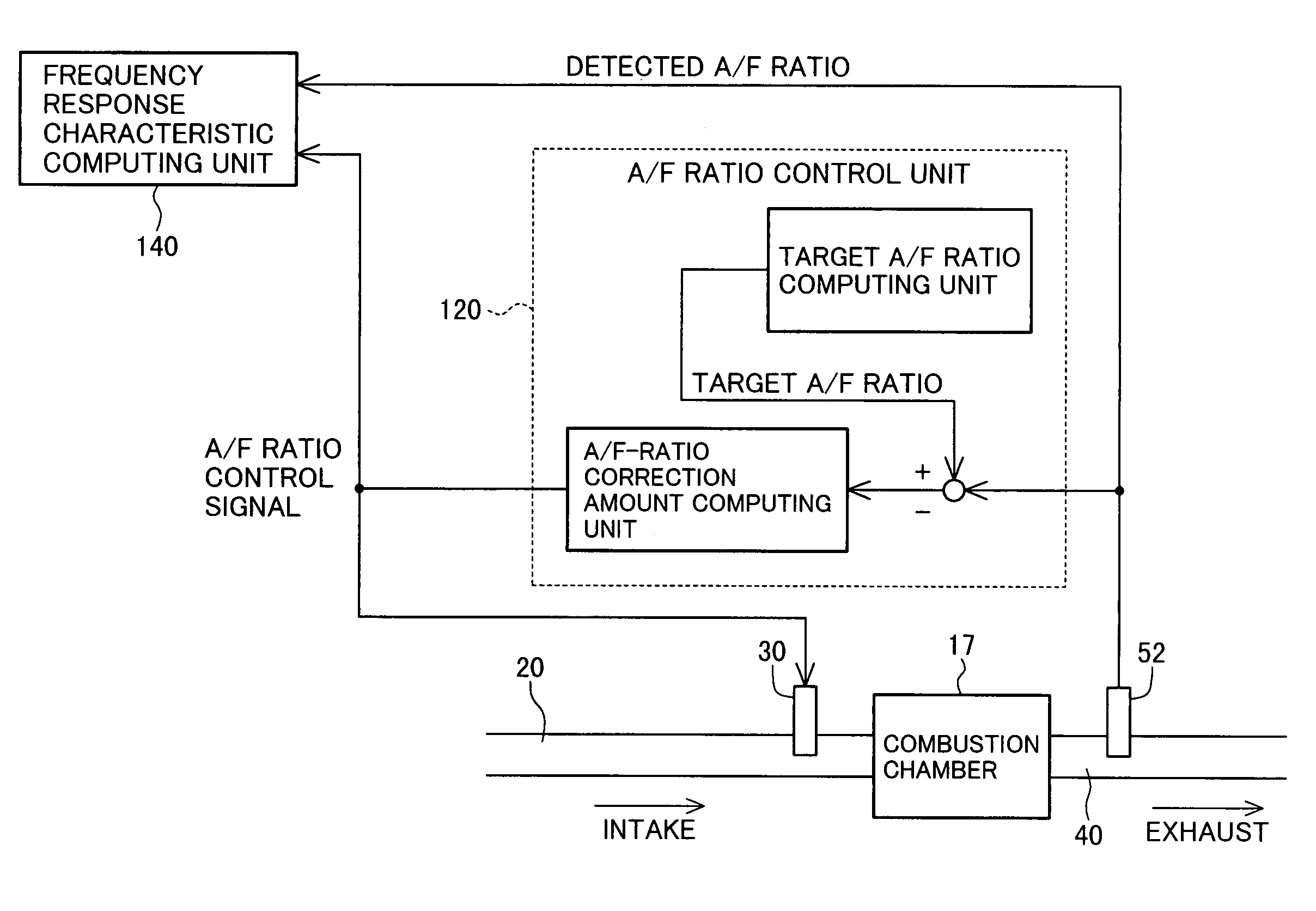
[0134]A second embodiment of the engine controller according to the present invention will be described below. Various components of the second embodiment are of substantially the same configurations as those of the above-described first embodiment (FIGS. 24 to 33) except for the A / F ratio control unit 120. Therefore, overlap of the description is avoided here and the A / F ratio control unit 120 used in the second embodiment will be described with reference to FIG. 34.

[0135]The A / F ratio control unit 120 of this second embodiment differs from the A / F ratio control unit 120 (FIG. 25) of the first embodiment in that the (all-cylinder) A / F ratio correction amount computing unit 122 is replaced by a first-cylinder A / F ratio correction amount computing unit 124 and the correction amount Chos is reflected only on the A / F ratio (fuel injection amount) of the first cylinder #1. The following description is made primarily of different points from the first embodiment.

124>

[0136]This computing ...

third embodiment

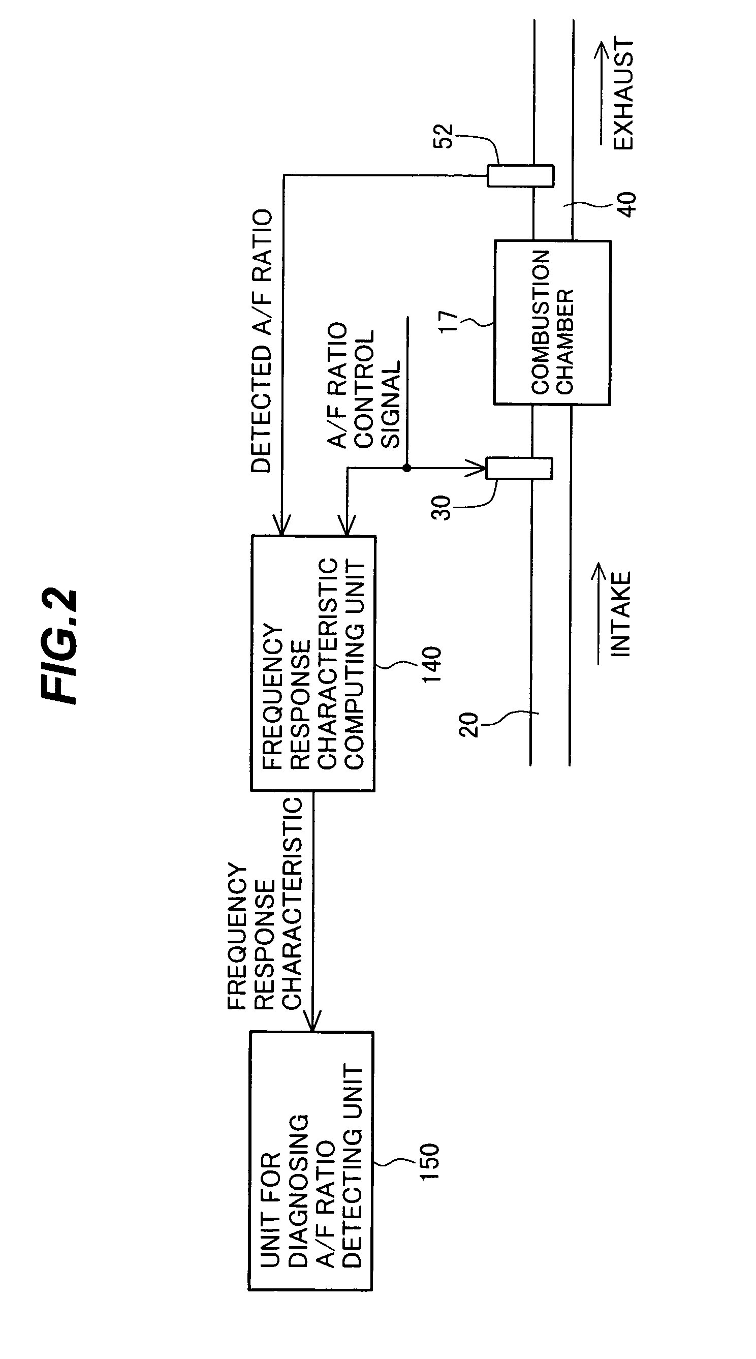
[0138]A third embodiment of the engine controller according to the present invention will be described below. Various components of the third embodiment are of substantially the same configurations as those of the above-described second embodiment (FIG. 34) except for only the processing procedures executed by the A / F sensor diagnosis unit 150. Therefore, the following description is made primarily of different points from the second embodiment.

150>

[0139]The A / F sensor diagnosis unit 150 in this third embodiment diagnoses the A / F sensor 52 by using Power(fa(Ne)) and Phase(fa(Ne)) both computed by the frequency response characteristic computing unit 140. In practice, as shown in FIG. 37, the diagnosis unit 150 computes a difference Δpower(fa) between the gain characteristic Power(fa(Ne)) and a gain characteristic reference value Power0. The gain characteristic reference value Power0 is decided in advance, for example, on the basis of a gain characteristic that is obtained under the o...


PUM


Abstract

The invention provides an engine controller, which can determine a deterioration mode (gain deterioration or response deterioration) of an air / fuel (A / F) ratio sensor, can detect a degree of the deterioration with high accuracy, and can optimize A / F ratio feedback control in accordance with the diagnosis result. The controller includes a unit for computing frequency response characteristics in a range from an A / F ratio adjusting unit to the A / F ratio sensor, and it diagnoses the A / F ratio sensor based on a gain characteristic and a response characteristic given by the computed frequency response characteristics. In accordance with the diagnosis result, parameters (P- and I-component gains) used in A / F ratio feedback control (PI control) are optimized.

Description

BACKGROUND OF THE INVENTION[0001]1. Field of the Invention[0002]The present invention relates to an engine controller including an air / fuel (A / F) ratio adjusting unit, such as a throttle valve and a fuel injector valve, for adjusting an A / F ratio of an air-fuel mixture subjected to combustion, and an A / F ratio detecting unit, such as a linear A / F ratio sensor, disposed in an exhaust passage. More particularly, the present invention relates to an engine controller capable of diagnosing, for example, whether the A / F ratio detecting unit has deteriorated or not, and optimizing A / F ratio control in accordance with the diagnosis result.[0003]2. Description of the Related Art[0004]Recently, controls on auto-emission have been tightened. To clean HC, CO and NOx exhausted from an engine, it has become general to dispose, in an exhaust passage, a three-way catalyst and, upstream of the catalyst, a linear A / F ratio sensor (hereinafter referred to as an “A / F sensor”) producing a linear output ...

Claims


Application Information

Patent Timeline
Patent Type & Authority Patents(United States)
IPC IPC(8): F02D41/14F02D41/30F02D9/02F02D41/00F02D41/22F02D41/34F02D45/00
CPCF02D41/1495F02D41/008F02D41/1454F02D41/1456F02D2041/1409F02D2041/1422F02D2041/288
Inventor NAKAGAWA, SHINJIIIHOSHI, YOUICHIKURASHIMA, YOSHIKUNIHORI, TOSHIO
Owner HITACHI ASTEMO LTD
Why Eureka
Try Eureka