Shaft seal mechanism, shaft seal mechanism assembling structure and large size fluid machine

a technology of shaft seal mechanism and assembly structure, which is applied in the direction of engine seals, leakage prevention, machines/engines, etc., can solve the problems of affecting the manufacture and use of devices, affecting the size of the entire shaft seal mechanism, and affecting the assembly of smaller shaft seal mechanisms into the stator

Active Publication Date: 2007-06-05
MITSUBISHI HEAVY IND LTD
View PDF22 Cites 43 Cited by
  • Summary
  • Abstract
  • Description
  • Claims
  • Application Information

AI Technical Summary

Benefits of technology

[0015]In view of the above-mentioned circumstances of the prior art, it is an object of the present invention to provide a means by which a desired seal performance can be stably obtained.

Problems solved by technology

(1) For a device in which the shaft seal mechanism (the leaf seal 1) is to be provided, there are strong demands to make the device compact, and efforts are being made for reducing the entire size of the shaft seal mechanism, for example by reducing the thickness. However, as mentioned below, assembly of a smaller shaft seal mechanism into the stator is difficult, which causes problems with the manufacture and employment of the device.
But to create such a shape of the concave groove in the stator is generally difficult, and even if a compact shaft seal mechanism is developed, there might be a case where actual employment thereof is difficult.
But if the thin plates 3 are smaller than the present size, there is a possibility that a desired seal performance may not be stably obtained.
If the rotating shaft 2 is rotating while such a strong contact is being maintained, there is a risk that the thin plates 3 and the rotating shaft 2 will be damaged.
However, at the present situation, because of various reasons, such as welding strain caused at the manufacturing time, excess torque of bolting, and working accuracy of the split leaf seal rings 5a, 5b, it is difficult to control the gap size formed between the thin plates 3 and the lower pressure side plate 8 to be maintained as designed.

Method used


Image

  • Shaft seal mechanism, shaft seal mechanism assembling structure and large size fluid machine
  • Shaft seal mechanism, shaft seal mechanism assembling structure and large size fluid machine
  • Shaft seal mechanism, shaft seal mechanism assembling structure and large size fluid machine

Examples


Embodiment Construction

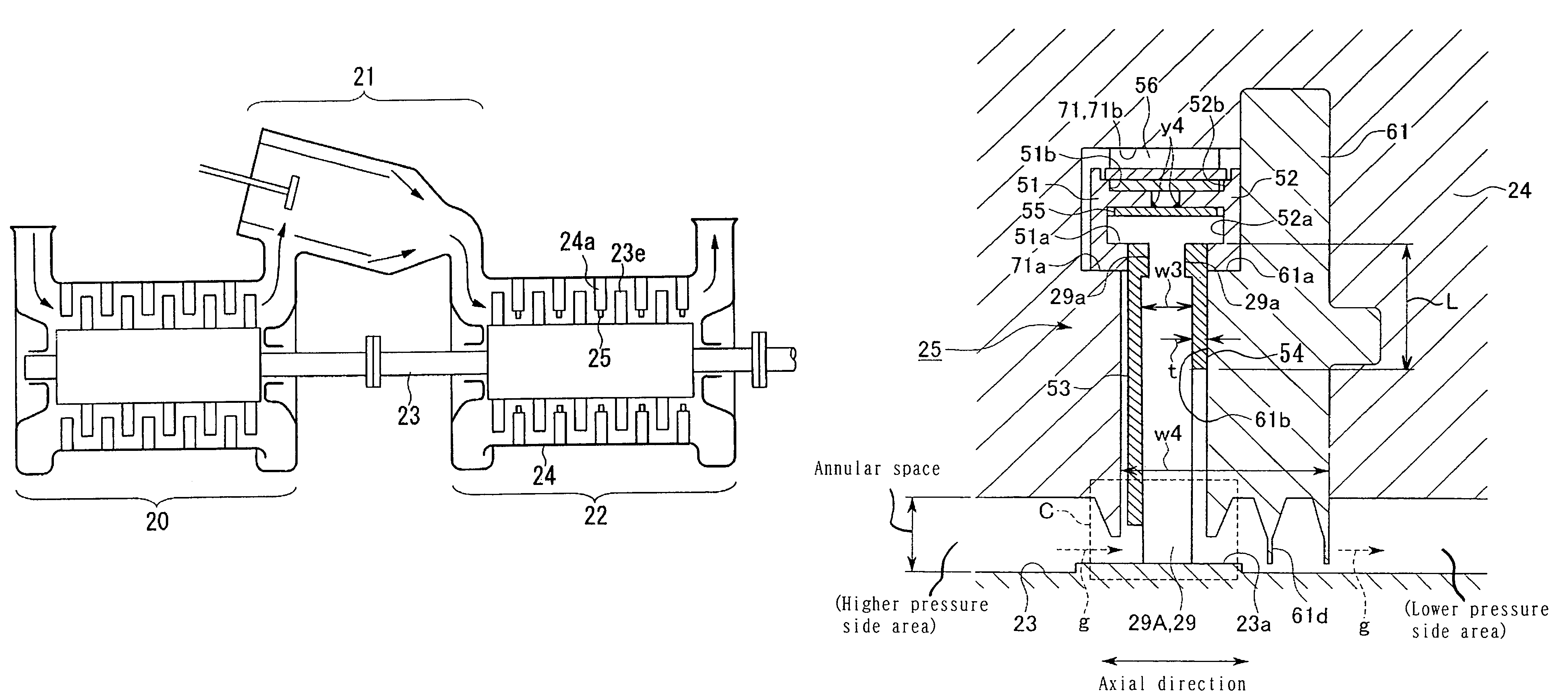
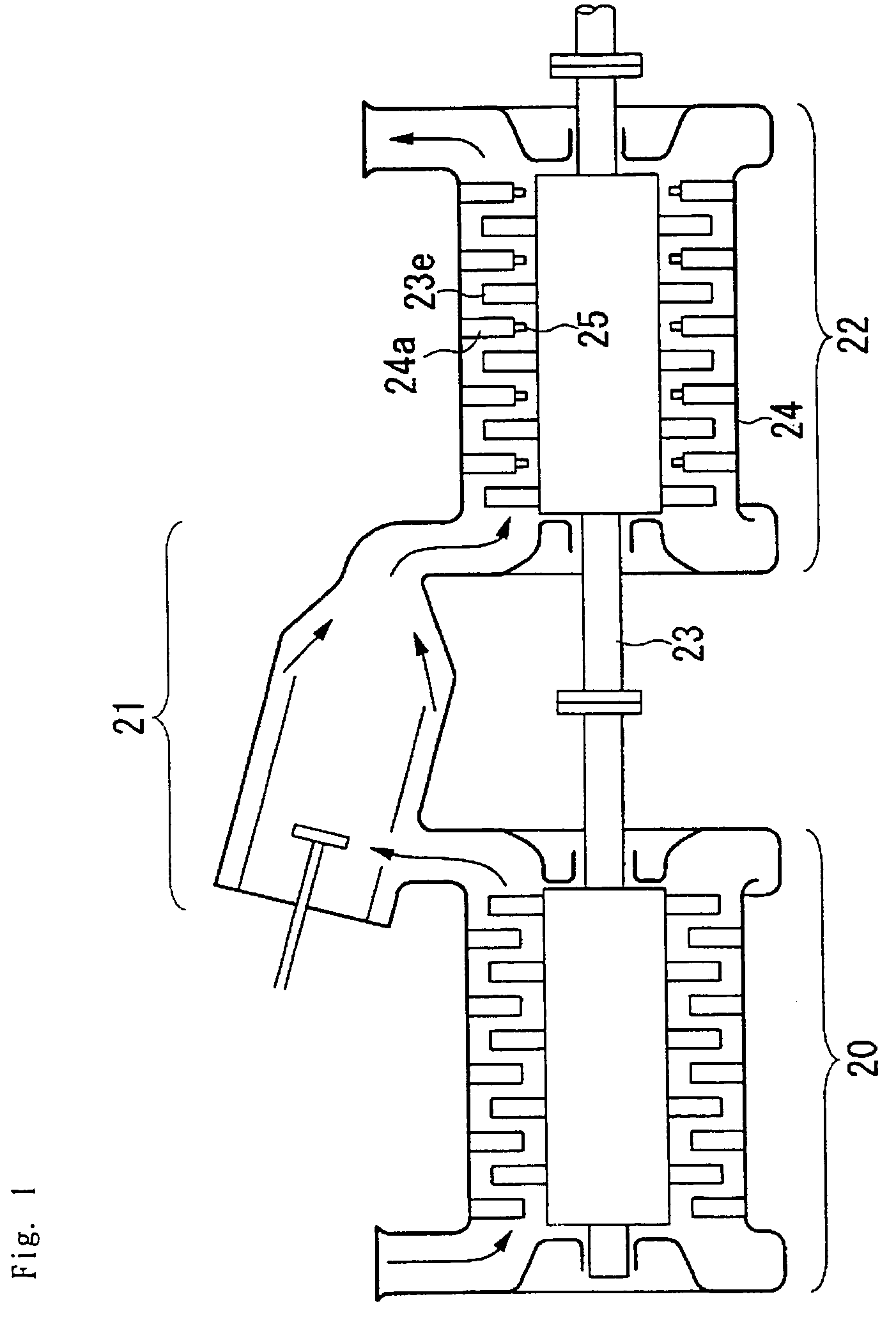
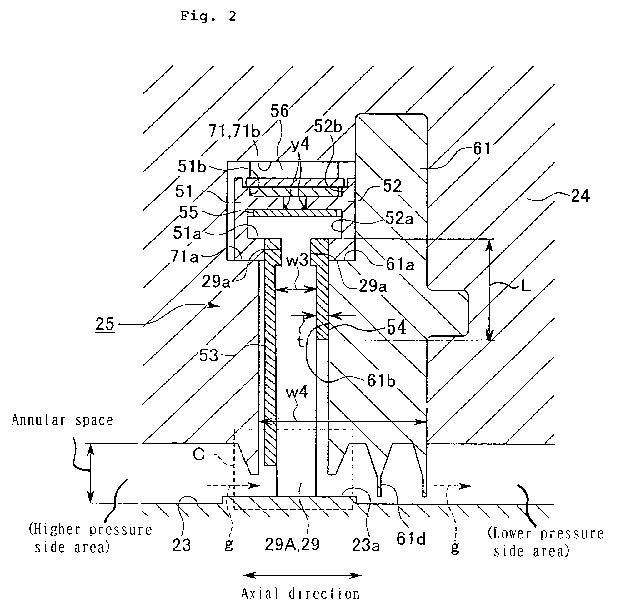
[0054]One embodiment of a gas turbine comprising a leaf seal (shaft seal mechanism) according to the present invention will be described with reference to appended drawings, provided that, as a matter of course, the present invention is not to be construed as limited to the present embodiment. Also, while the present embodiment will be described with respect to an example where a large size fluid machine to which the present invention is applied is a turbine of a gas turbine, the present invention is also applicable to a rotating shaft or the like of a large size fluid machine, such as a steam turbine, compressor, water turbine, refrigerator, pump, aero gas turbine engine or the like.

[0055]FIG. 1 is a schematic constructional cross sectional view showing the embodiment of a gas turbine comprising a leaf seal (shaft seal mechanism) according to the present invention. In FIG. 1, numeral 20 designates a compressor, numeral 21 a combustor, numeral 22 a turbine and numeral 24 a stator. T...


PUM


Abstract

A shaft seal mechanism (leaf seal) by which a desired seal performance can be stably obtained is provided. The shaft seal mechanism comprises a concave groove 71 formed larger than a minimum size of a plate width of thin plates 29 and a fitting piece 61 fitted in a gap between the concave groove 71 and a leaf seal 25. The leaf seal 25 comprises an annular thin plate assembly 29A constructed by the thin plates 29 and a plate spring 56 integrally formed therewith supporting the annular thin plate assembly 29A to be levitated coaxially with a rotating shaft 23. The thin plates 29 have their outer circumferential proximal end side made movable relative to the concave groove 71. A shaft seal mechanism assembling structure is also provided comprising a pressure receiving surface 61b and a lower pressure side plate 54 forming a predetermined gap size between the pressure receiving surface 61b and one side edges of the thin plates 29.

Description

BACKGROUND OF THE INVENTION[0001]1. Field of the Invention[0002]The present invention relates to a shaft seal mechanism appropriately used for a rotating shaft or the like of a large size fluid machine, such as a gas turbine, steam turbine, compressor, water turbine, refrigerator, pump or the like and also relates to a shaft seal mechanism assembling structure and large size fluid machine both using this shaft seal mechanism.[0003]2. Description of the Prior Art[0004]Generally, a shaft seal mechanism is provided around a rotating shaft of a gas turbine, steam turbine or the like, for reducing leakage of working fluid leaking to a lower pressure side from a higher pressure side. As one example of such a shaft seal mechanism, a known leaf seal is shown in the Japanese laid-open patent application 2002-13647.[0005]FIG. 9 is a cross sectional view of one example of a prior art leaf seal (shaft seal mechanism) of the kind mentioned above, wherein this leaf seal is seen on a cross section...

Claims


Application Information

Patent Timeline
Patent Type & Authority Patents(United States)
IPC IPC(8): F01D11/02F16J15/44F16J15/447F16J15/32
CPCF16J15/3292F16J15/4472
Inventor NAKANO, TAKASHISHIRAI, HIROKAZUASADA, TOSHIONISHIMOTO, SHINSHINOHARA, TANEHIROUEHARA, HIDEKAZU
Owner MITSUBISHI HEAVY IND LTD
Why Eureka
Try Eureka