
Ink-jet recording process

a technology of recording process and inkjet, applied in the direction of inks, instruments, printing, etc., can solve the problems of insufficient fixing ability, image irregularity, failure to obtain satisfactory images, etc., and achieve the effect of sacrificing both fixing ability and coloring property

Inactive Publication Date: 2007-06-05
CANON KK
View PDF29 Cites 4 Cited by
  • Summary
  • Abstract
  • Description
  • Claims
  • Application Information

AI Technical Summary

Benefits of technology

The present invention provides an ink-jet recording process that can solve the problem of color bleeding and show through in a recording medium while maintaining fixing ability and coloring properties. The process involves ejecting a pigment ink and a reaction liquid containing a polyvalent metal salt from a recording section, in which a plurality of nozzles for ejecting the pigment ink and the reaction liquid are arranged. The conditions for ejecting the reaction liquid are determined based on the surface tension of the reaction liquid and the print resolution in both the direction of scanning and the arrangement direction of the nozzles. The process allows for the formation of a filmy aggregate at the interface where the reaction liquid and the pigment ink meet, resulting in improved coloring and reduced bleeding.

Problems solved by technology

When such an ink is used to conduct recording on plain paper, there have hence arisen such problems as fixing ability cannot be sufficiently achieved, and image irregularity occurs, which appears to be attributed to the uneven distribution of a filler and / or a size on the surface of the paper.
Therefore, color bleeding and uneven color mixing have occurred at portions of boundaries between images of different colors (this phenomenon will hereinafter be referred to as “bleeding” simply), resulting in a failure to obtain satisfactory images.
However, such disadvantages that the image density and brightness of the resulting image are lowered, and the image shows through a recording medium to the back side thereof have been involved because coloring materials contained in the inks penetrate deeply into the recording medium.
In addition, such inks have not been preferred because they are easy to be spread due to the improvement of wettability on the recording medium, resulting in reduction of resolution and occurrence of feathering.
However, according to this method, it is feared that a problem that fixing ability is lowered due to poor drying ability of the solution itself will arise though anti-bleeding property is improved.
Therefore, a problem that the coloring property of the resulting image is not improved, and a problem of the show through that the coloring material is shown through from the back side of the recording medium have arisen.
As described above, when the color ink is reacted with the reaction liquid at the time the reaction liquid is present on the recording medium, the fixing ability of the resulting image is deteriorated.
When the reaction liquid is reacted with the color ink at the time the reaction liquid is present in the recording medium on the other hand, it is feared that a problem that coloring property is deteriorated will arise.
However, problems of deterioration of coloring property and the show through are feared when the penetrability of the color ink into the recording medium is high.
When the penetrability is low to the contrary, it is feared that a problem that fixing requires a long time may arise.
As a result, a larger amount of a solvent comes to be present in printed areas of the secondary color and tertiary color, so that fixing requires a longer time.
On the other hand, the fixing ability is deteriorated when importance is attached to the coloring property and the show through.

Method used


Image

  • Ink-jet recording process
  • Ink-jet recording process
  • Ink-jet recording process

Examples


Embodiment Construction

[0074]The present invention will hereinafter be described in more detail by the preferred embodiments of the invention. An ink-jet recording process that is a prerequisite of the present invention will be first described with reference to FIGS. 12A to 12F, FIGS. 13A to 13D, FIGS. 14A and 14B, and FIG. 15.

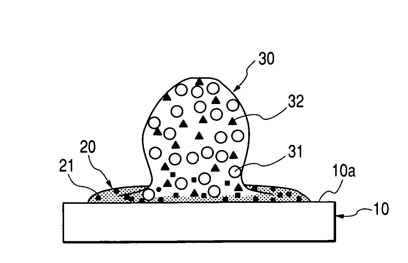
[0075]FIGS. 12A to 12F typically illustrate the concept of a fundamental ink-jet recording process that is a prerequisite of the present invention. FIG. 12A illustrates a step of bringing a reaction liquid 20 into contact with a pigment ink 30 on the surface of a recording medium 10 and shows the instant when the pigment ink 30 came into contact with the reaction liquid 20 by applying the pigment ink 30 to the recording medium 10, on which the reaction liquid 20 had been applied in advance. Incidentally, in this embodiment, the penetrability of the pigment ink is made higher than that of the reaction liquid from the viewpoints of bringing the reaction liquid into contact with the pi...


PUM

PropertyMeasurementUnit
sizeaaaaaaaaaa
viscosityaaaaaaaaaa
specific surface areaaaaaaaaaaa

Abstract

Disclosed herein is an ink-jet recording process for conducting recording by ejecting a pigment ink and a reaction liquid containing a polyvalent metal salt from a recording section, in which a plurality of nozzles for ejecting the pigment ink and the reaction liquid are arranged, to a recording medium while relatively scanning the recording section to the recording medium, comprising the steps of ejecting the pigment ink having a surface tension lower than that of the reaction liquid to the reaction liquid ejected on the surface of the recording medium; and forming a filmy aggregate by gathering of agglomerates at an interface where the reaction liquid has come into contact with the pigment ink, wherein conditions for ejecting the reaction liquid to a prescribed area on the recording medium when at least the print duty of the ink in the prescribed area is 100% satisfy the relationship of55×0.85×106×Vd⁡(pl)-0.61Rx⁡(dpi)⁢Ry⁡(dpi)≤duty⁡(%)≤125×0.85×106×Vd⁡(pl)-0.61Rx⁡(dpi)⁢Ry⁡(dpi)wherein Vd(pl) is an ejection volume per dot of the reaction liquid, Rx(dpi) is a print resolution in the direction of the relative scanning, Ry(dpi) is a print resolution in the arrangement direction of the nozzles, and duty(%) is a print duty of the reaction liquid.

Description

BACKGROUND OF THE INVENTION[0001]1. Field of the Invention[0002]The present invention relates to an ink-jet recording process, and particularly to an ink-jet recording process that can provide a high-quality color image high in fixing ability on plain paper.[0003]2. Related Background Art[0004]An ink-jet recording method is such a method that recording is conducted by ejecting minute droplets of an ink to apply the ink to a recording medium such as paper. According to the method (see, for example, Japanese Patent Publication Nos. 61-59911, 61-59912 and 61-59914), in which an electrothermal converter is used as an ejection energy-supplying means to apply thermal energy to ink so as to generate bubbles, thereby ejecting droplets of the ink, the formation of a high-density multi-orifice in a recording head can be realized with ease, and high-resolution and high-quality images can be recorded at high speed.[0005]However, the conventional inks used in ink-jet recording generally comprise...

Claims


Application Information

Patent Timeline
Patent Type & Authority Patents(United States)
IPC IPC(8): B41J2/01B41M5/00B41M7/00C09D11/00
CPCB41M5/0017B41M7/0018C09D11/30C09D11/54
Inventor NAKAZAWA, KOICHIROISHIKAWA, TAKUEI
Owner CANON KK
Learn More