

Transmit based equalization using a voltage mode driver
- Summary
- Abstract
- Description
- Claims
- Application Information
AI Technical Summary
Benefits of technology
Problems solved by technology
Method used
Image


Examples
Embodiment Construction
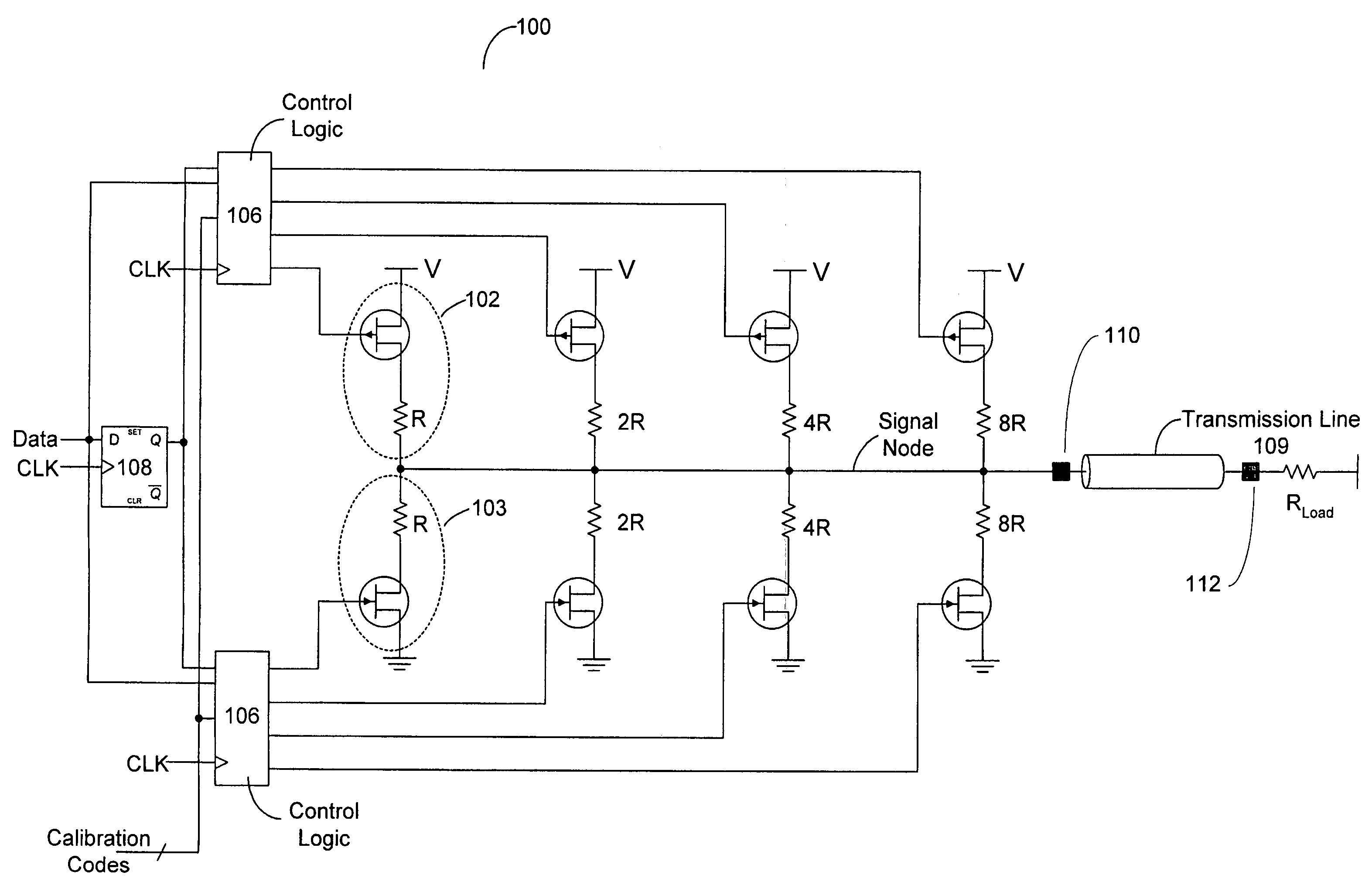
[0024]Turning now to FIG. 2, a schematic diagram of one embodiment of a driver circuit is shown. In the embodiment shown, driver circuit 100 includes a plurality of pull-up circuits 102 and a plurality of pull-down circuits 103. Each pull-up circuit 102 includes a transistor (a field effect transistor, or FET for this embodiment) and a resistor. First and second terminals (e.g., a source and drain, respectively, in this example) of the transistor of each pull-up circuit 102 are coupled between a voltage node and a first terminal of a pull-up resistor. A second terminal of the pull-up resistor is coupled to a signal node.
[0025]Driver circuit 100 also includes a plurality of pull-down circuits. Each pull-down circuit 103 includes a transistor (also a FET in this embodiment) having a first terminal coupled to a reference node (e.g., a ground node) and a second terminal coupled to a first terminal of a pull-down resistor. A second terminal of the pull-down resistor is coupled to the sig...
PUM
 Abstract
Description
Claims
Application Information