Synchronizing pulse generating method and method of receiving OFDM signal

Inactive Publication Date: 2007-06-05
TCL COMM TECH HLDG
View PDF26 Cites 28 Cited by
  • Summary
  • Abstract
  • Description
  • Claims
  • Application Information

AI Technical Summary

Benefits of technology

[0018]If desired, the timing pulse could be generated at any time during the window which represents maximum correlation, for example at the middle of this window. As the signal conditions vary, this point may shift, in which case the synchronisation pulse will alter accordingly. In the preferred embodiment, however, the timing of the synchronisation pulse is altered only if certain conditions are met. For example, the timing can be altered only if the current timing is found to be in error a predetermined number of times, and/or only if the current error exceeds a predetermined amount. This technique, which is regarded to be an independently inventive aspect, avoids excessive numbers of changes in the timing of the Fourier Transform operation, each of which would cause a phase rotation of each of the carriers at the output of the FFT by a different angle, which would place a heavy workload on the channel estimator conventionally provided.
[0019]According to a still further aspect of the invention, there is provided at the output of the FFT means for imparting different phase rotations to the respective samples

Problems solved by technology

Although these operate adequately in common reception conditions, there are circumstances in which the timing pulse is generated at an undesirable point, leading to ISI.
In some circumstances, this will result in the timing pulse being provided outside the optimum window, thus resulting in ISI.
This can also result in the synchronisation pulse being generated outside the optimum window in the case of significant noise or multi-path interference.
Furthermore, a PLL requires a substantial number of symbol periods in order to achieve lock, w

Method used


Image

  • Synchronizing pulse generating method and method of receiving OFDM signal
  • Synchronizing pulse generating method and method of receiving OFDM signal
  • Synchronizing pulse generating method and method of receiving OFDM signal

Examples


Example

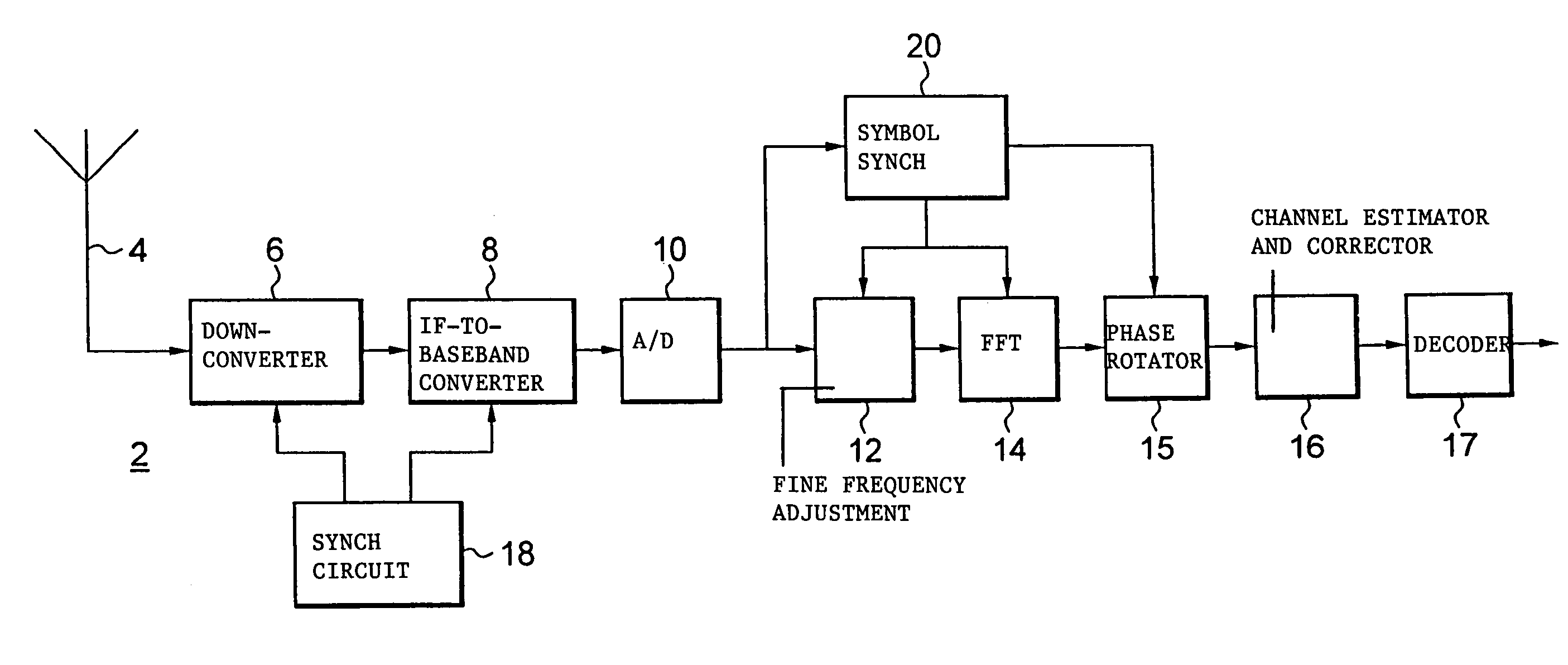
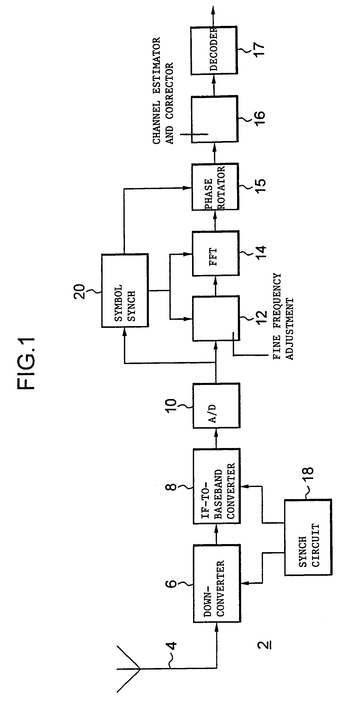
[0030]Referring to FIG. 1, an OFDM receiver 2 comprises an antenna 4 which receives a signal and presents it to a down-converter 6 which converts the RF signal to an IF signal. This is then converted into a baseband signal by an IF-to-baseband converter 8. This produces at its output complex samples of each transmitted OFDM symbol. These complex samples are digitised by an analog-to-digital (A / D) converter 10, and delivered via a fine frequency adjustment circuit 12 to a Fast Fourier Transform (FFT) circuit 14. The FFT circuit 14 converts the samples from the time domain to the frequency domain, and the symbol data at the output is provided to a phase rotator 15, a channel estimator and corrector 16 and a decoder 17.

[0031]The techniques of the present invention facilitate the provision of a feed-forward system, which doesn't rely on feedback or phase locked loops (PLL's) for adjusting the local oscillator frequencies. However, it would be possible in an alternative arrangement if de...


PUM


Abstract

In an OFDM receiver, a synchronisation pulse for defining a Fast Fourier Transform window is generated by examining the output of a correlator to find a sub-interval within which there is maximum correlation between samples of the symbol separated by the length of the useful part of the symbol. The synchronisation pulse is generated during this sub-interval (102). Adjustments to the timing of the synchronisation pulse are made only if the current error is significant and persistent. A signal representing the amount of adjustment is used to determine phase rotations applied to the output of the FFT circuit.

Description

TECHNICAL FIELD[0001]This invention relates to OFDM modulation. It is particularly concerned with the generation of a synchronisation pulse representing an OFDM symbol boundary, for example for use in Fourier Transform demodulation.BACKGROUND ART[0002]OFDM systems are well known. Various techniques have been used for synchronisation of OFDM receivers. Some of these techniques require transmission of a special synchronisation signal. Other techniques rely on a standard OFDM signal, in which a complete symbol comprises a “useful part” and a “guard space”, the guard space sometimes being referred to as a guard interval, cyclic extension or cyclic prefix.[0003]The guard space precedes the useful part of the symbol and contains a repeat of the data at the end of the useful part. (This is equivalent to having a guard space after the useful part, containing data which is the same as that at the beginning of the useful part.)[0004]Synchronisation techniques which rely upon the duplicated da...

Claims


Application Information

Patent Timeline
IPC IPC(8): H04J11/00H04J3/06H04L27/26
CPCH04L27/2665H04L27/2676
Inventor BARTON, STEPHEN K.BRUNT, STEPHEN M.ECHAVARRI, JAVIERORRISS, JOHN
Owner TCL COMM TECH HLDG
Why Eureka
Try Eureka