
Biomass gasification system

a gasification system and biomass technology, applied in the field of biomass gasification, can solve the problems of low value of these products in the market of today's market, insufficient capital and operating costs of conventional biomass gasification systems, and inability to efficiently extract heat energy from biomass materials, etc., to achieve the effect of reducing maintenan

Inactive Publication Date: 2007-06-12
INNOVAAT COM INT INC
View PDF13 Cites 24 Cited by
  • Summary
  • Abstract
  • Description
  • Claims
  • Application Information

AI Technical Summary

Benefits of technology

[0019]A second object is to provide a biomass gasification system for efficiently extracting heat energy from biomass material.
[0025]Another object is to provide a biomass gasification system that is automated and requires reduced maintenance.

Problems solved by technology

The main problems with the application of biomass gasification systems have been economic, not technical.
For example, conventional biomass gasification systems are typically suitable only for large-scale operations and not small-scale operations.
Also, the product from gasification is mainly a heat source, and the low value of these products in today's market is insufficient to justify the capital and operating costs of conventional biomass gasification systems.
However, the Berg et al. patent reference does not have a piston feeder structure, a rotating grate within the primary combustion chamber, a silica collector system nor an oxygen mixer between the primary combustion chamber and the secondary combustion chamber.
While these devices may be suitable for the particular purpose to which they address, they are not as suitable for efficiently extracting heat energy from biomass material.
Conventional biomass apparatus do not efficiently extract heat energy from the biomass material.

Method used


Image

  • Biomass gasification system
  • Biomass gasification system
  • Biomass gasification system

Examples


Embodiment Construction

A. Overview

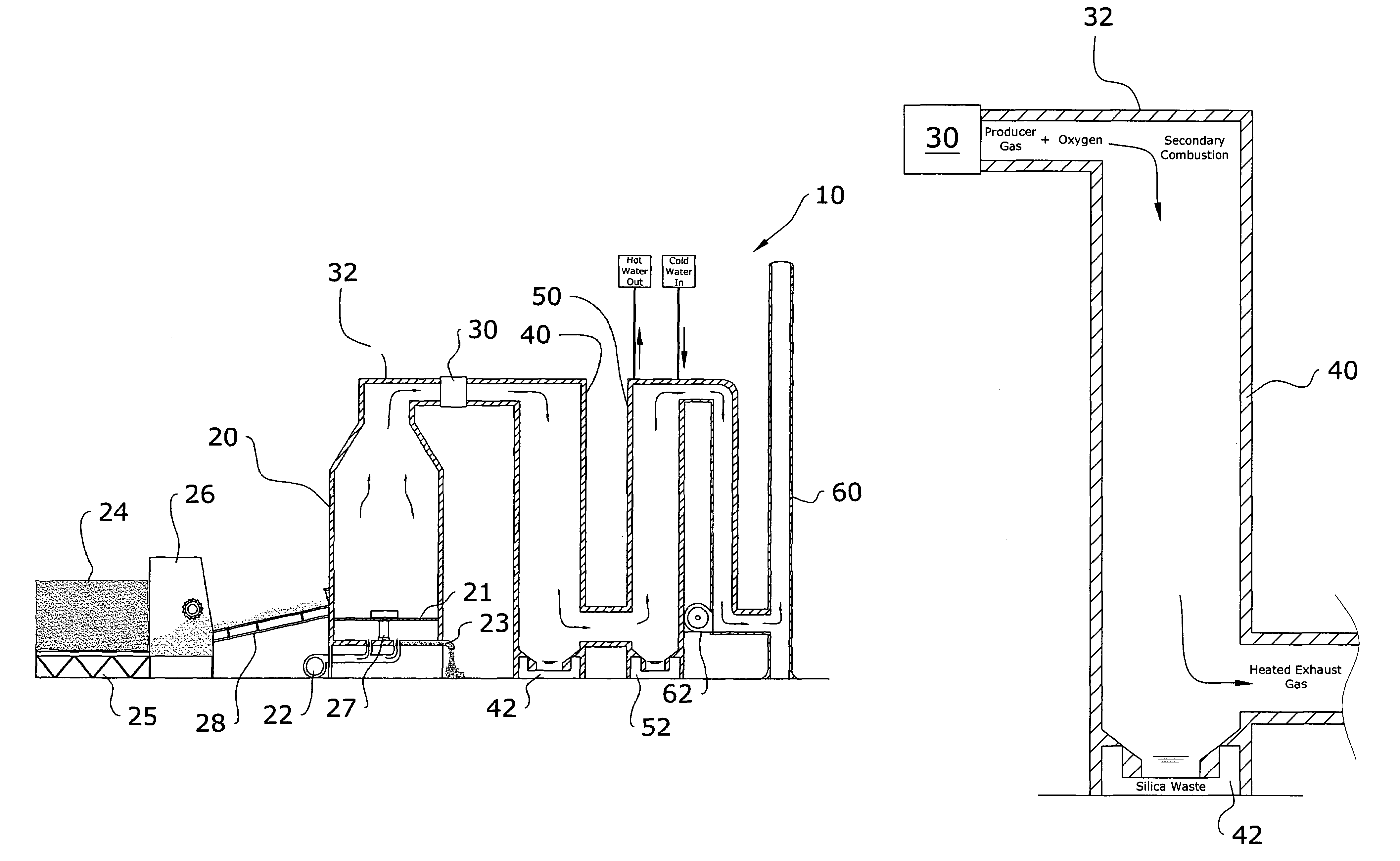
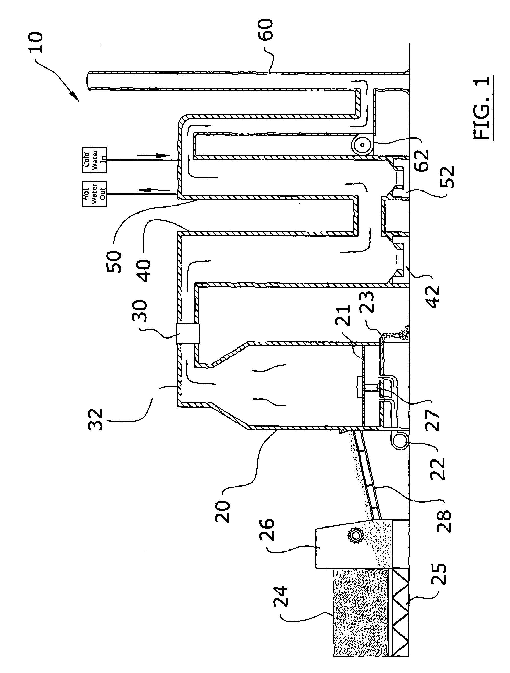
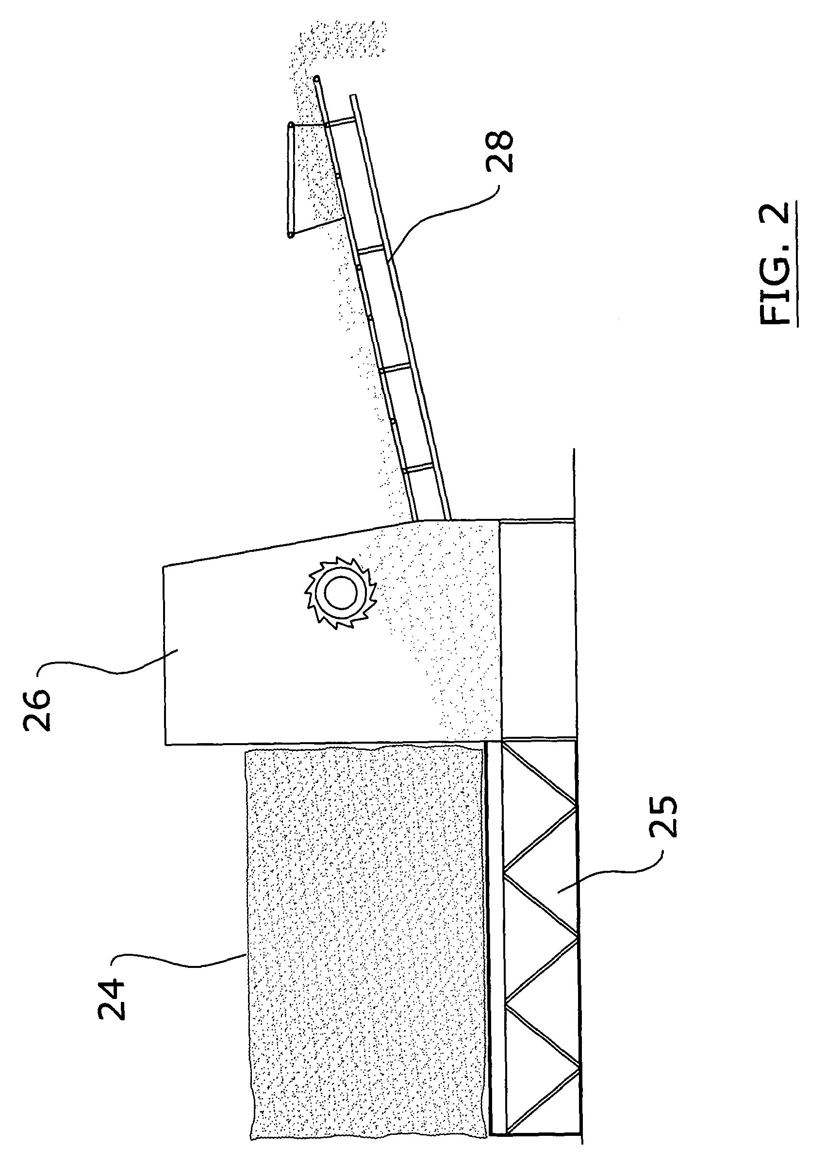
[0040]Turning now descriptively to the drawings, in which similar reference characters denote similar elements throughout the several views, FIGS. 1 through 10 illustrate a biomass gasification sysem 10, which comprises a primary combustion chamber 20, a rotating grate 21 within the primary combustion chamber 20 for supporting the biomass during gasification, a feeder unit 70 in communication with the primary combustion chamber 20 for delivering biomass, a secondary combustion chamber 40 fluidly connected to the primary combustion chamber 20, an oxygen mixer 30 positioned between the primary combustion chamber 20 and the secondary combustion chamber 40, a heat exchanger 50 and an exhaust stack 60.

B. Primary Combustion Chamber

[0041]The primary combustion chamber 20 is where the primary combustion occurs thereby converting the biomass to a producer gas as shown in FIGS. 1, 3 and 8 of the drawings. The primary combustion chamber 20 may be comprised of various structures comm...


PUM


Abstract

A biomass gasification system for efficiently extracting heat energy from biomass material. The biomass gasification system includes a primary combustion chamber, a rotating grate within the primary combustion chamber for supporting the biomass during gasification, a feeder unit in communication with the primary combustion chamber for delivering biomass, a secondary combustion chamber fluidly connected to the primary combustion chamber, an oxygen mixer positioned between the primary combustion chamber and the secondary combustion chamber, a heat exchanger and an exhaust stack.

Description

CROSS REFERENCE TO RELATED APPLICATIONS[0001]Not applicable to this application.STATEMENT REGARDING FEDERALLY SPONSORED RESEARCH OR DEVELOPMENT[0002]Not applicable to this application.BACKGROUND OF THE INVENTION[0003]1. Field of the Invention[0004]The present invention relates generally to biomass gasification and more specifically it relates to a biomass gasification system for efficiently extracting heat energy from biomass material.[0005]2. Description of the Related Art[0006]Biomass gasification processes have been in use for years for converting biomass into an energy source. Biomass gasification applications include water boiling, steam generation, drying, motive power applications (e.g. using the producer gas as a fuel in internal combustion engines), and electricity generation.[0007]Almost all kinds of biomass with moisture content of 5–30% can be gasified. Examples of suitable biomass include forest slash, urban wood waste, lumber waste, wood chips, sawdust, straw, firewood...

Claims


Application Information

Patent Timeline
Patent Type & Authority Patents(United States)
IPC IPC(8): F23D1/00F23G7/10F23G7/00F23G5/00F23G5/027F23G5/44F23G5/46
CPCF23B1/24F23B90/06F23G5/027F23G5/444F23G5/46F23G7/10F23G2201/303F23G2201/40F23G2205/10Y02E20/12
Inventor DUECK, RAYMONDWIERZBOWSKI, MACIEJ G.
Owner INNOVAAT COM INT INC
Learn More