Electrostatic valves for microfluidic devices

a technology of microfluidic devices and electrostatic valves, which is applied in the direction of valves, mechanical devices, engine components, etc., can solve the problems of large and complex designs, limited bulk and surface micro-machining methods, and each of these conventional approaches suffers from its own limitations

Inactive Publication Date: 2007-06-19
CALIFORNIA INST OF TECH
View PDF119 Cites 140 Cited by
  • Summary
  • Abstract
  • Description
  • Claims
  • Application Information

AI Technical Summary

Problems solved by technology

However, each of these conventional approaches suffers from its own limitations.
A limitation of the first approach of silicon-based micro-machining is that the stiffness of the semiconductor materials used may necessitate high actuation forces, which in turn result in large and complex designs.
In fact, both bulk and surface micro-machining methods are limited by the stiffness of the materials used.
In addition, adhesion between various layers of the fabricated device is also a problem.
On the other hand, when surface micro-machining, thermal stresses between the various layers of the device limits the total device thickness, often to approximately 20 μm.

Method used


Image

  • Electrostatic valves for microfluidic devices
  • Electrostatic valves for microfluidic devices
  • Electrostatic valves for microfluidic devices

Examples


first embodiment

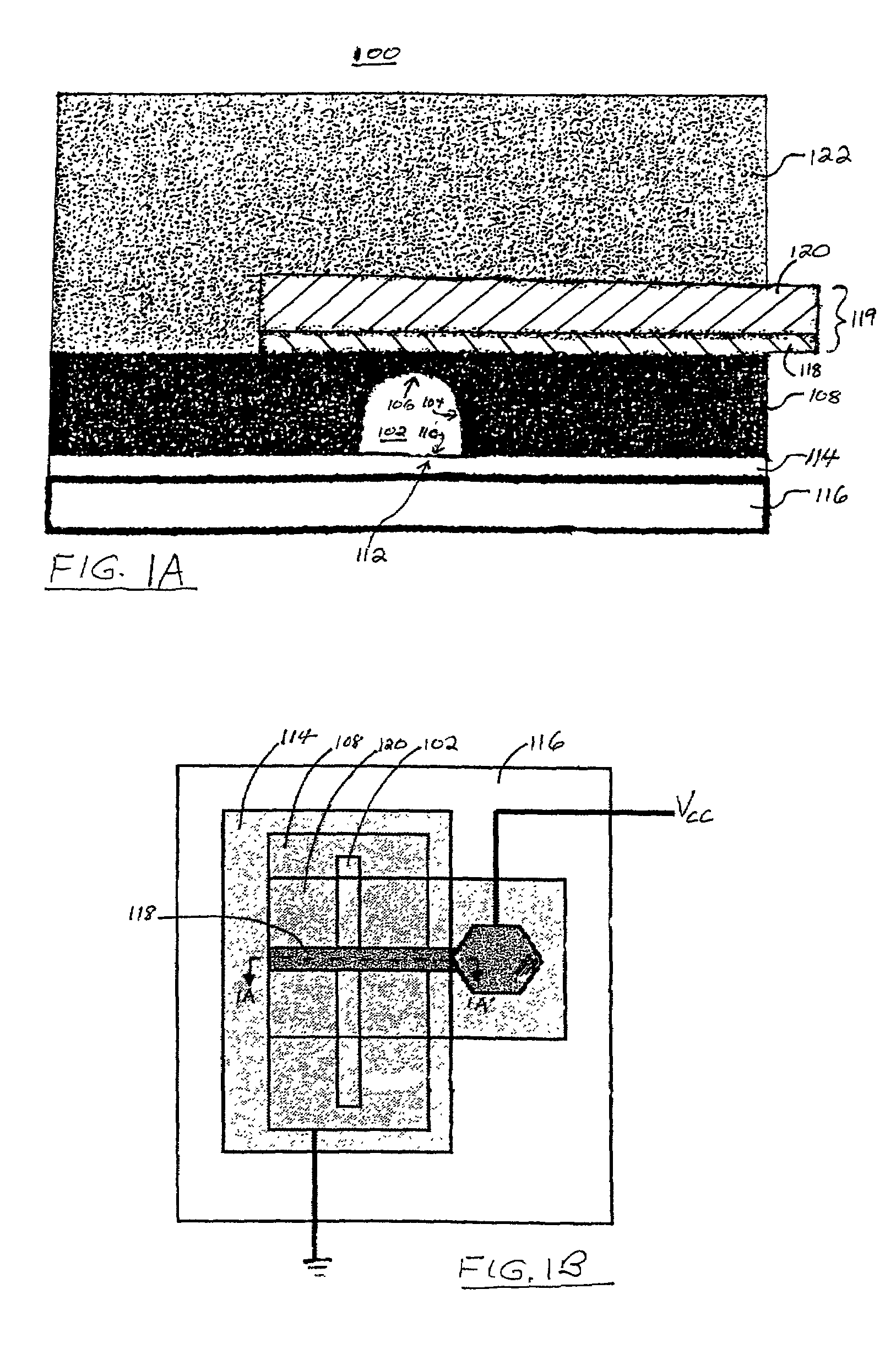
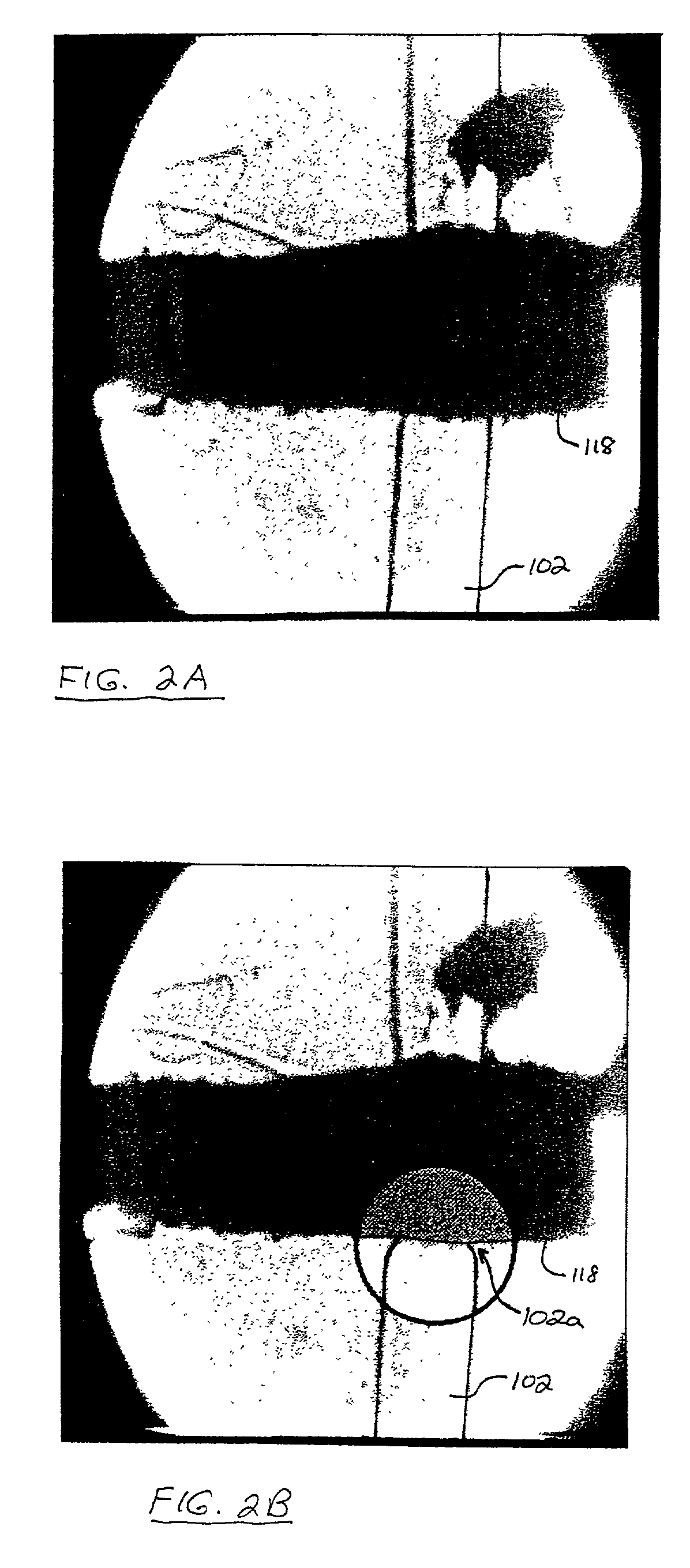
I. First Embodiment of a Valve Structure in Accordance with the Present Invention

[0018]A. Sources of Materials

[0019]RTV 615(™) polydimethylsulfoxide (PDMS) was obtained from General Electric. Pyralux(®) LF 9110 copper / polyimide laminate was obtained from DuPont. Photoresist 5740(™) and Developer CD 20 (™) were obtained from Shipley Microelectronics. Trimethylchlorosilane (TMCS) and FeCl3 were obtained from Sigma. Hexamethyldisilazine (HMDS) was obtained from ShinEtsuMicrosi of Phoenix, Ariz.

[0020]B. Fabrication of Mold

[0021]A silicon wafer was exposed to HMDS, and then Photoresist 5740 was spun upon a silicon wafer at 2000 rpm for 60 sec. The photoresist / wafer combination was then baked at 95° C. for 60 min. The coated wafer was exposed to UV light through a mask for 2.3 min. to create exposed photoresist regions having widths varying between 30-250 μm. Development of the photoresist with 20% CD20(™) resulted in removal of unexposed photoresist. The wafer and patterned exposed photo...

second embodiment

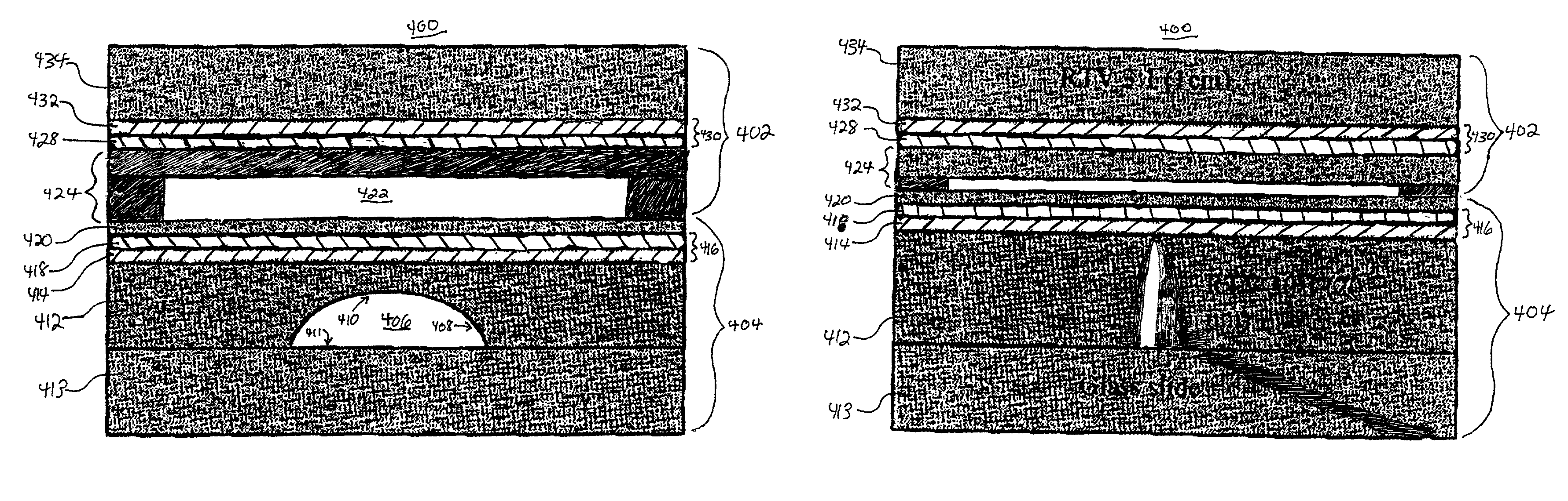
II. Second Embodiment of a Valve Structure in Accordance with the Present Invention

[0044]While embodiments of valve structures described above in connection with FIGS. 1A-3 utilize flexible electrical control wires fabricated from copper / polyimide laminate layers overlying the flow channel, the present invention is not limited to this particular structure. Other structures and / or materials could be utilized to control the flow liquid and gaseous materials, and still remain within the scope of the present invention.

[0045]For example, in both embodiments described above in conjunction with FIGS. 1A-3, an electric field is applied across the flow channel during actuation of the valve structure. However, in an electric field ions present in the flow channel may migrate to a side of the flow channel proximate to one of the charged poles (wire or electrode). This possible migration of charged species could affect the magnitude of the electrostatic force applied to the valve.

[0046]In addit...


PUM

PropertyMeasurementUnit
thicknessaaaaaaaaaa
widthaaaaaaaaaa
widthaaaaaaaaaa

Abstract

Valve structures formed in elastomer material are electrostatically actuated by applying voltage to a flexible, electrically conductive wire pattern. An actuation force generated between the patterned wire structure and an electrode result in closure of a flow channel formed in elastomer material underlying the wire. In one embodiment of a valve structure in accordance with the present invention, the wire structure is patterned by lithography and etching of a copper / polyimide laminate, with an underlying gold plate positioned on the opposite side of the flow channel serving as an electrode. In an alternative embodiment, a first wire structure is patterned by physically cutting out a first pattern of strips from an Aluminum / Mylar(®) laminate sheet. A second patterned wire structure serving as the electrode is formed by the same method, and positioned on the opposite side of a control channel. Application of an actuation force between the first and second patterned strips closes the control channel and an associated flow channel underlying the control channel.

Description

CROSS-REFERENCE TO RELATED APPLICATION[0001]This nonprovisional patent application claims priority from provisional patent application No. 60 / 246,469, filed Nov. 6, 2000. The text of this provisional patent application is hereby incorporated by reference.STATEMENT AS TO RIGHTS TO INVENTIONS MADE UNDER FEDERALLY SPONSORED RESEARCH AND DEVELOPMENT[0002]Work described herein has been supported, in part, by Air Force Research Organization grant DAAD 19-00-1-0392. The United States Government may therefore have certain rights in the invention.BACKGROUND OF THE INVENTION[0003]Pumps and valves for transporting and manipulating liquids in microfluidic devices are essential for developing lab on a chip technology. Various approaches to designing micro-fluidic pumps and valves have been attempted. However, each of these conventional approaches suffers from its own limitations.[0004]The two most common methods of producing microelectromechanical (MEMS) structures such as pumps and valves are s...

Claims


Application Information

Patent Timeline
Patent Type & Authority Patents(United States)
IPC IPC(8): F16K31/02F15C5/00F16K99/00
CPCF15C5/00F16K31/02F16K99/0001F16K99/0011F16K99/0051F16K2099/0074F16K2099/0078F16K2099/008B33Y80/00
Inventor DRIGGS, B. SCOTTENZELBERGER, MARKUS M.QUAKE, STEPHEN R.
Owner CALIFORNIA INST OF TECH
Why Eureka
Try Eureka