Integrated all-Si capacitive microgyro with vertical differential sense and control and process for preparing an integrated all-Si capacitive microgyro with vertical differential sense

a capacitive microgyro and vertical differential sense technology, applied in the direction of instruments, acceleration measurement using interia forces, devices using electric/magnetic means, etc., can solve the problems of high manufacturing cost of microgyroscopes, inability to integrate control electronics with silicon structures, and high manufacturing cost of resonators. to achieve the effect of improving vibration immunity

Inactive Publication Date: 2007-06-19
HRL LAB
View PDF31 Cites 39 Cited by
  • Summary
  • Abstract
  • Description
  • Claims
  • Application Information

AI Technical Summary

Benefits of technology

[0016]For improved vibration immunity, a set of control and sense electrodes located above the resonator offers advantages. This invention refers to a method for adding an array of bump bonds on the base wafer that then forms electrical interconnects to the top electrodes when the capping wafer is bonded to the base wafer. A cut-out in the resonator frame allows the interconnects to be connected to the top electrodes without having to transverse deep groves. The height of the added bump bonds are adjustable to be equal to the metal seal ring on the base wafer so that vacuum sealing and top electrode connection is performed in the same bonding step.

Problems solved by technology

The manufacturing of the resonator involves high fabrication costs.
The known manufacturing processes make it very difficult to manufacture a microgyroscope.
The central post is inserted by hand, the device has to be vacuum packaged in a custom package and there is no ability to integrate control electronics with the silicon structure.

Method used


Image

  • Integrated all-Si capacitive microgyro with vertical differential sense and control and process for preparing an integrated all-Si capacitive microgyro with vertical differential sense
  • Integrated all-Si capacitive microgyro with vertical differential sense and control and process for preparing an integrated all-Si capacitive microgyro with vertical differential sense
  • Integrated all-Si capacitive microgyro with vertical differential sense and control and process for preparing an integrated all-Si capacitive microgyro with vertical differential sense

Examples


Embodiment Construction

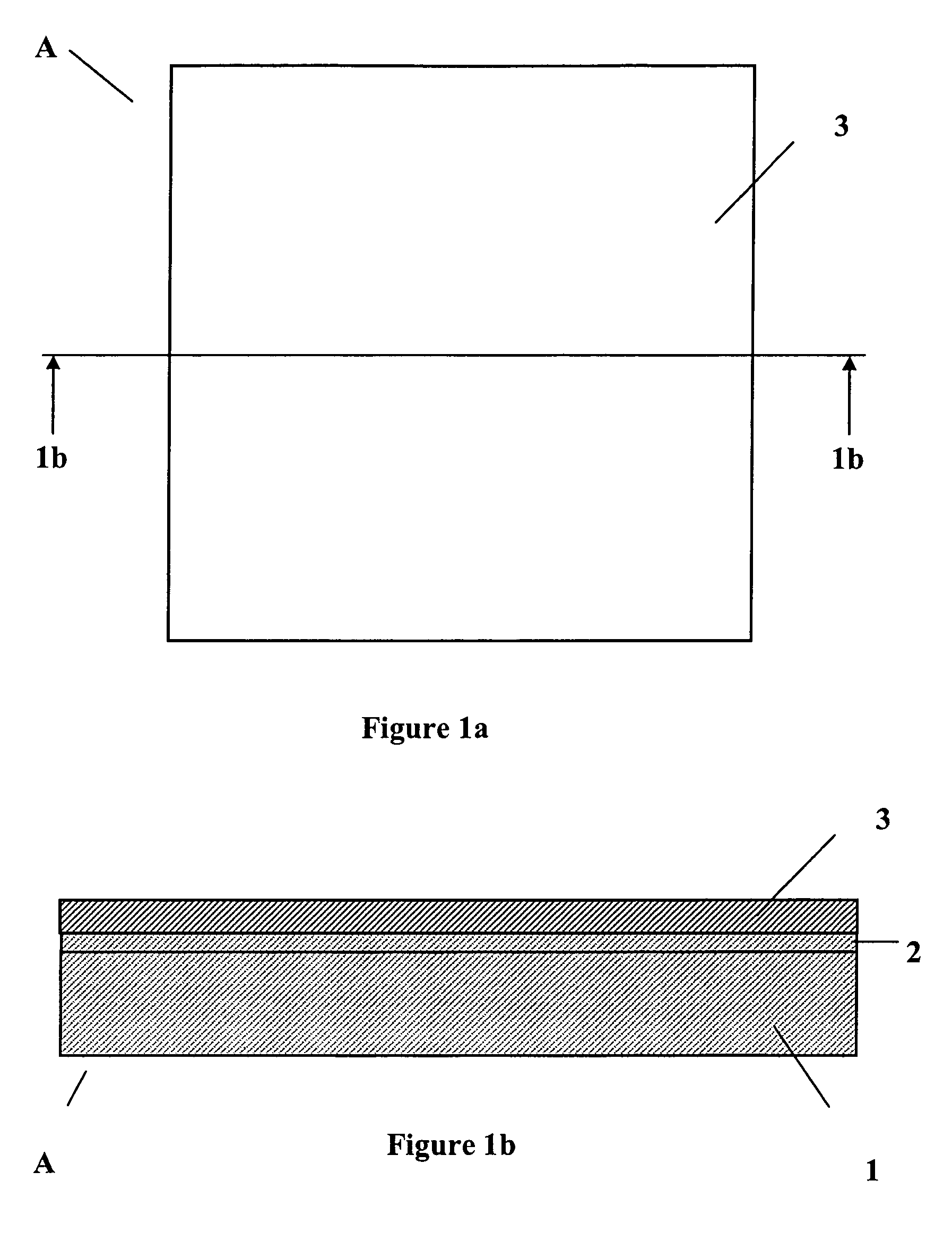
[0047]The resonator wafer A, preferably a silicon-on-insulator (SOI) wafer, is preferably prepared first. On a bulk silicon base 1 having a preferable thickness of ≦500 μm, which is optionally lightly-doped bulk silicon about 1e15 cm−3, a silicon dioxide layer 2 having a preferable thickness of ≦2 μm is formed preferably by thermal oxidation at a temperature between 800° C. and 1000° C. On top of the silicon dioxide layer 2 a heavily doped silicon epi-layer, p-type, 1e19–1e20 cm−3 3 is preferably provided having a preferable thickness of 10 μm to 20 μm, as shown in FIGS. 1a and 1b.

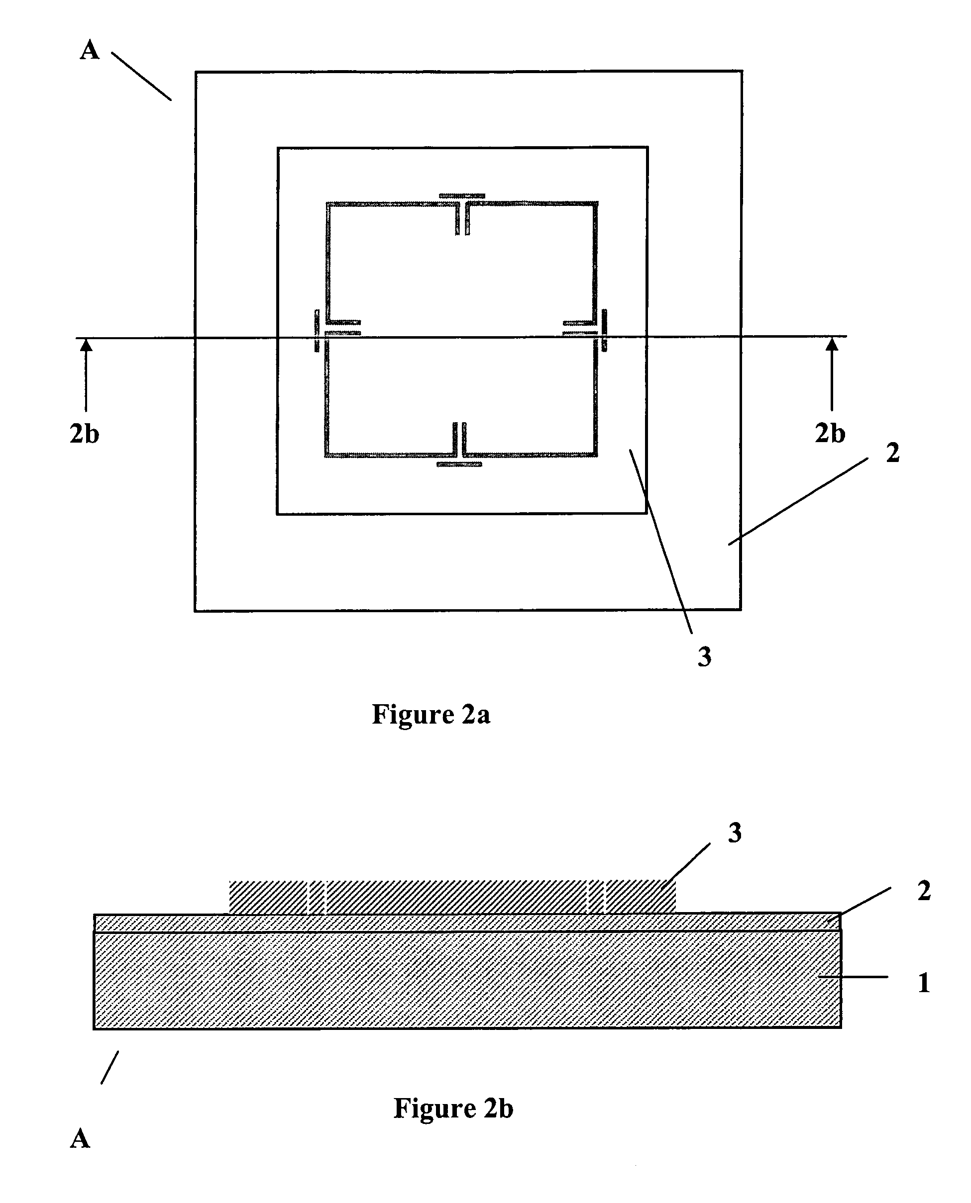
[0048]Then the cloverleaf petal and spring of the resonator wafer A is prepared. Parts of the heavily-doped silicon epi-layer 3 are removed, preferably by photoresist lithography, deep reactive ion etching (DRIE) and photoresist removal, as shown in FIGS. 2a and 2b. Photoresist lithography and DRIE are described in inter alia Veljko Milanovic et al. “Deep Reactive Ion Etching for Lateral Field Emission De...


PUM


Abstract

The present invention relates to a method of manufacturing a cloverleaf microgyroscope containing an integrated post comprising: attaching a post wafer to a resonator wafer, forming a bottom post from the post wafer being attached to the resonator wafer, attaching the resonator wafer to a base wafer, wherein the bottom post fits into a post hole in the base wafer, forming a top post from the resonator wafer, wherein the bottom and top post are formed symmetrically around the same axis, preparing a cap with backside metallization, and attaching a cap wafer on top of the base wafer. The present invention relates further to a gyroscope containing an integrated post with on or off-chip electronics.

Description

BACKGROUND OF THE INVENTION[0001]1. Field of the Invention[0002]The present invention refers to an integrated all-Si capacitive microgyroscope with vertical differential Sense and Control and process for preparing an integrated all-Si capacitive microgyro with vertical differential Sense.[0003]2. Description of Related Art[0004]U.S. Pat. No. 5,894,090 to Tang et al., which is incorporated herein by reference, discloses a micromachined symmetrical leaf structure having a plurality of symmetrically disposed leaves about a defined center. At least one micromachined spring is disposed symmetrically with respect to the symmetrical leaf structure and supporting the symmetrical leaf structure, a rim / base structure to which the spring is coupled. The rim / base structure includes a plurality of sensing and drive electrodes and a circuit electrically coupled to the electrodes included within the rim / base structure. The circuit provides drive signals to the drive electrodes to oscillate the sym...

Claims


Application Information

Patent Timeline
Patent Type & Authority Patents(United States)
IPC IPC(8): H01L21/00
CPCG01C19/5719
Inventor KUBENA, RANDALL L.
Owner HRL LAB
Why Eureka
Try Eureka