Pressure detecting apparatus

a technology of pressure detecting apparatus and detecting device, which is applied in the direction of instruments, semiconductor devices, measurement devices, etc., can solve the problems of poor thermal response of such devices, and achieve the effects of excellent thermal response, excellent elongation characteristics, and convenient absorbing of exerted stress

Active Publication Date: 2007-06-26
FUJI ELECTRIC CO LTD
View PDF4 Cites 6 Cited by
  • Summary
  • Abstract
  • Description
  • Claims
  • Application Information

AI Technical Summary

Benefits of technology

[0018]Since the pressure detecting means and the base means are connected and fixed to each other with the connecting means exhibiting an elongation percentage of about 400% or higher, the pressure detecting apparatus according to the invention that facilitates absorbing the exerted stress based on the excellent elongation characteristics exhibits excellent thermal response.
[0019]The pressure detecting apparatus according to the invention that exhibits excellent thermal response facilitates realizing a structure immune to temperature changes caused in the measurement environment and obtaining measurement results with very high reproducibility.

Problems solved by technology

In the pressure detecting apparatus, the thermal response thereof is not good, variations are caused between the initial detection performances and the detection performances after a temperature change is caused.

Method used


Image

  • Pressure detecting apparatus
  • Pressure detecting apparatus
  • Pressure detecting apparatus

Examples


Embodiment Construction

[0027]Now the invention will be described in detail hereinafter with reference to the accompanied drawings which illustrate the preferred embodiments of the invention. In the descriptions of the embodiments and the drawings illustrating the embodiments, the same reference numbers are used to designate the same of like constituent elements and their duplicated explanations are omitted for the sake of simplicity.

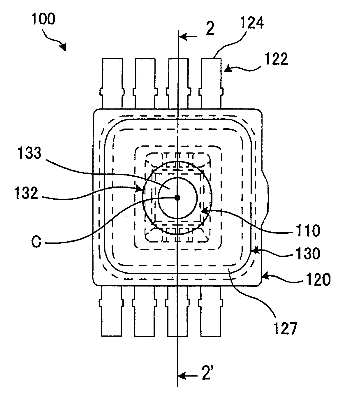
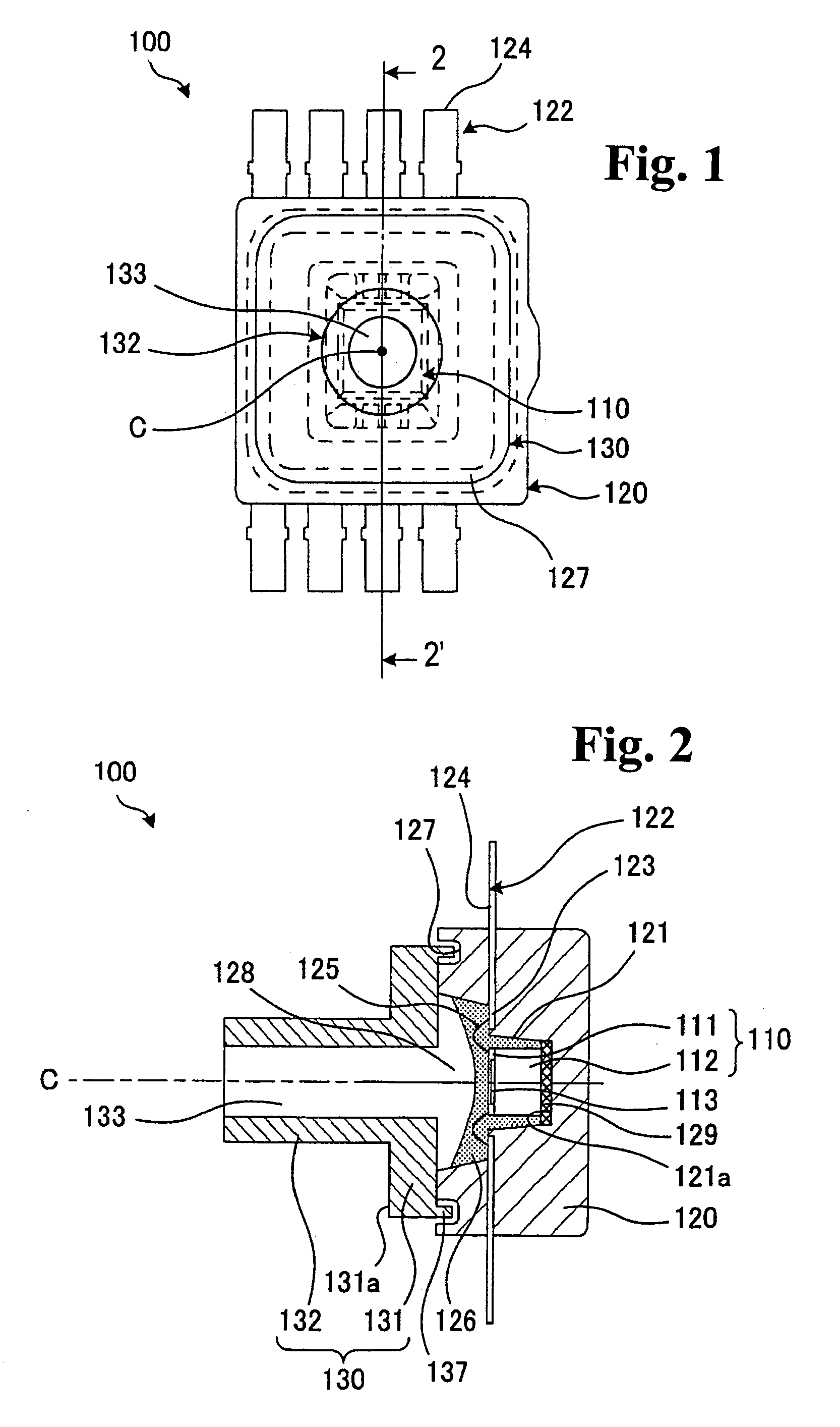
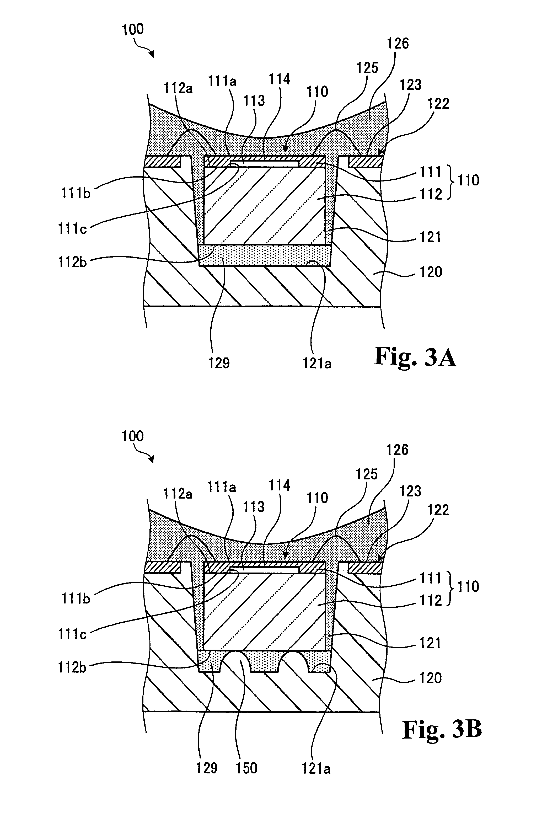
[0028]FIG. 1 is a top plan view of a pressure detecting apparatus according to a first embodiment of the invention. FIG. 2 is a cross-sectional view along the line segment 2–2′ in FIG. 1. FIG. 3A is an expanded cross-sectional view of a part of FIG. 2. FIG. 3B is a cross-sectional view showing a modification of the structure shown in FIG. 3A. In the following, the invention will be described with reference to FIGS. 1 through 3B as far as any specific explanation is not made and the reference numbers designating the constituent elements not illustrated in the drawings will not ...


PUM

PropertyMeasurementUnit
tensile elongation percentageaaaaaaaaaa
distanceaaaaaaaaaa
distanceaaaaaaaaaa

Abstract

A pressure detecting apparatus has a pressure detecting device that converts a strain caused by a stress exerted thereto to an electrical signal, and outputs the converted electrical signal. The apparatus has a housing base including a housing recess that houses the pressure detecting device therein, and a connecting material interposed between the pressure detecting device and the housing recess. The connecting material connects the pressure detecting device and the housing recess with a tensile elongation percentage of about 400% or higher. The pressure detecting apparatus facilitates preventing thermal stress from adversely affecting the detection performance thereof, and produces excellent thermal response.

Description

BACKGROUND OF THE INVENTION AND RELATED ART STATEMENT[0001]The present invention relates to a pressure detecting apparatus that converts the pressure detected thereby to an electrical signal and outputs the converted electrical signal. Specifically, the present invention relates also to a pressure detecting apparatus that exhibits excellent thermal response.[0002]Usually, the semiconductor pressure sensor chip that employs the so-called piezoresistance effects has been used for a pressure detecting apparatus for measuring the intake air pressure on the air intake side of an engine in the electronic controlled fuel injection apparatus for automobiles. Since the operational principles of the pressure detecting apparatus that employs the semiconductor pressure sensor chip as described above are well known, the detailed descriptions thereof are omitted. The pressure detecting apparatus includes a bridge circuit consisting of semiconductor strain gauges formed on a diaphragm made of a ma...

Claims


Application Information

Patent Timeline
Patent Type & Authority Patents(United States)
IPC IPC(8): G01L9/00
CPCG01L19/0084G01L19/147G01L19/146G01L19/143H01L2224/83385H01L2224/48091H01L2924/15156H01L2924/00014H01L29/84
Inventor SAITO, KAZUNORIICHIMURA, YUJIYAMAGUCHI, KEIUEYANAGI, KATSUMICHISHINODA, SHIGERU
Owner FUJI ELECTRIC CO LTD
Why Eureka
Try Eureka