
Measuring head for a gas analyser

Inactive Publication Date: 2007-06-26
PHASE IN
View PDF12 Cites 20 Cited by
  • Summary
  • Abstract
  • Description
  • Claims
  • Application Information

AI Technical Summary

Benefits of technology

[0011]Accordingly, the object of the present invention is to provide a novel arrangement with which all of the gases occurring in respiratory care can be analysed by a main flow measuring process in a sensor that is placed totally in the close proximity of the patient's mouth or trachea and that can be readily adapted to different care systems, e.g. to personal computers, monitoring instruments, without needing to be provided with special electronics or to be adapted mechanically to the measuring head used, and also to enable the measuring heads to be readily switched between different care systems in the absence of separate calibration systems or calibration procedures.

Problems solved by technology

For reasons of a technical nature, it has been difficult to develop main flow measuring patient-gas analysers other than for carbon dioxide.
Although such analysers have found a broad use spectrum in emergency care in particular, the use of lateral flow measuring analysers has been referred to in other care aspects, such as intensive care and anaesthesia, for instance, due to the occurrence of technical problems, primarily related to moisture and bacteria in the patient's respiratory circuit.
Moreover, it has been difficult to develop sufficiently small main flow measuring gas-flow analysers.
Such solutions have made the analyser more expensive, in addition to making service more troublesome and requiring the two parts to be calibrated with respect to one another.
However, intensity losses in the beam splitter and the size of the beam splitter make this type of analyser unsuitable for the multigas analysis based on main flow.
Unfortunately, oxygen gas exhibits no marked absorption within the infrared range and, in respect of oxygen gas analysis, there are normally used fuel cells or analysers that utilise the paramagnetic properties of oxygen gas.
These latter solutions are highly “shock”-sensitive, which makes them unsuitable for main flow measuring analysis.
Response times of such long duration have made it difficult to use fuel cells for registration of oxygen gas that is dissolved during main flow measuring gas analysis.

Method used


Image

  • Measuring head for a gas analyser
  • Measuring head for a gas analyser
  • Measuring head for a gas analyser

Examples


Embodiment Construction

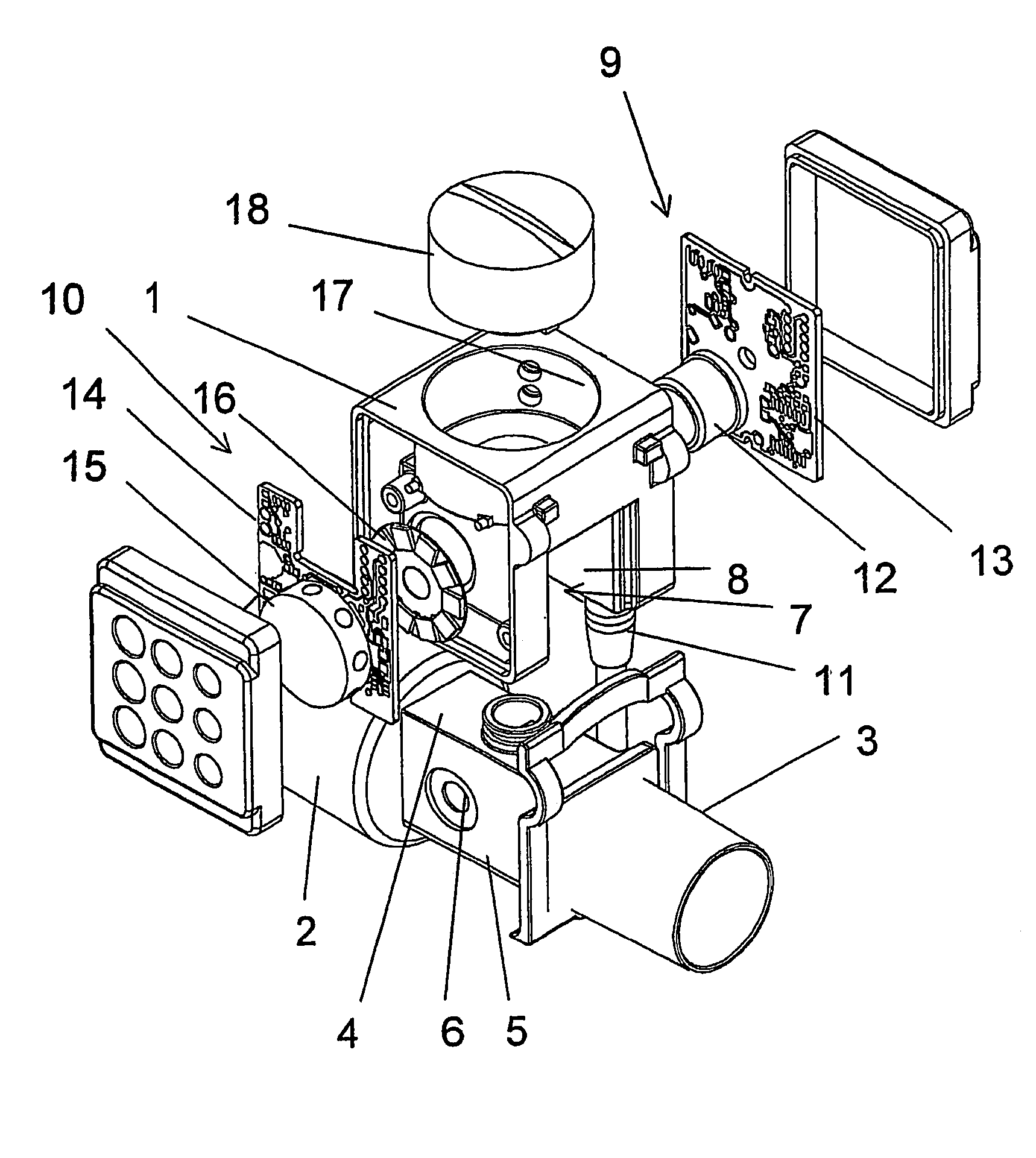
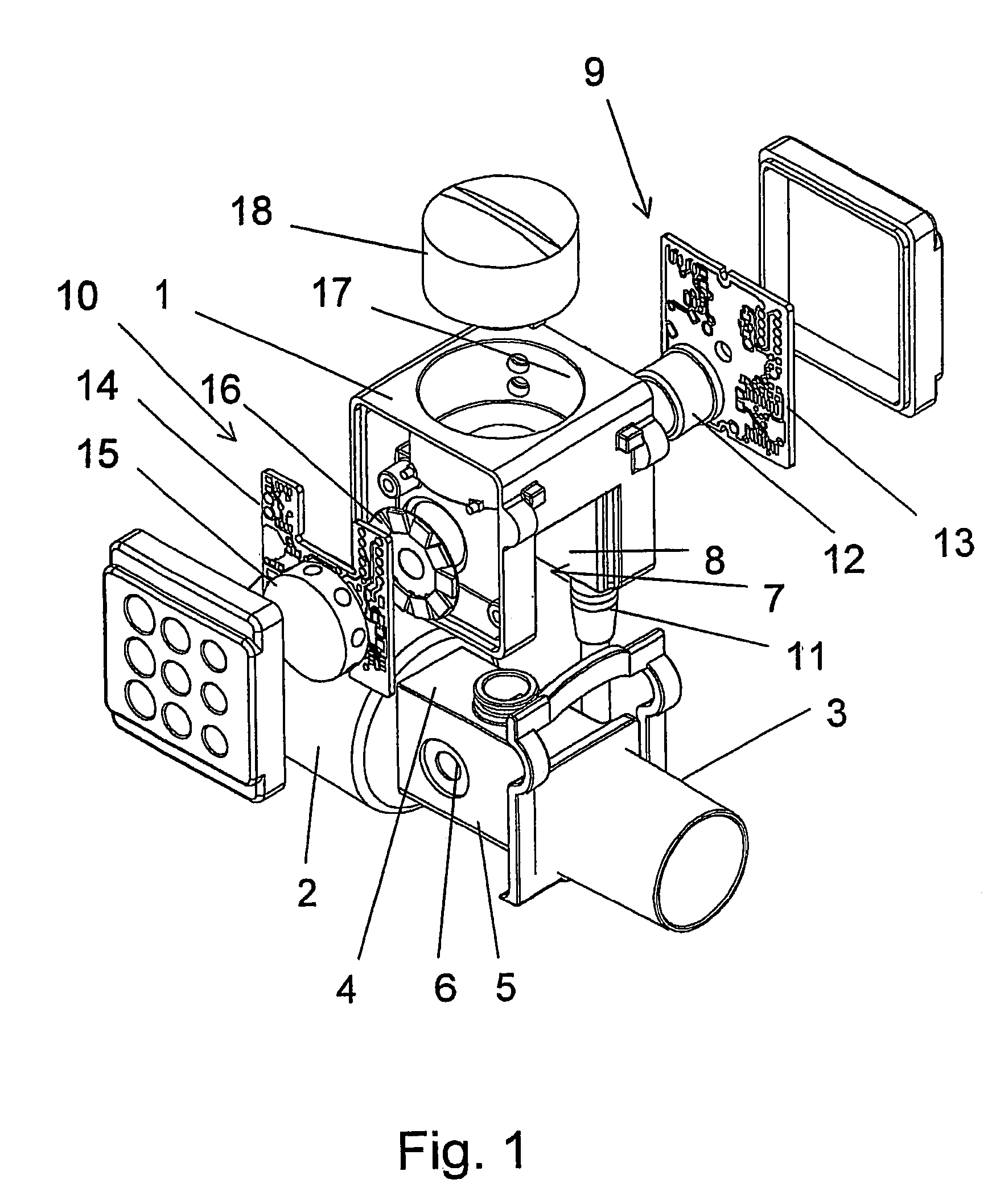
[0016]Thus, FIG. 1 shows a gas analyser measuring head 1 which is intended to be fitted onto an adapter 2. The adapter can be seen mainly as an elongate tube comprised, for instance, of plastic material. The adapter 2 carries at one end a connector for connection to a hose that leads to the patient and at the other end a connector 3 for connection to a respirator or the like. The adapter includes between the two connectors a central portion 4 that is designed to accommodate the measuring head 1. The central portion 4 includes to this end two mutually opposing planar sides 5, each of which includes a window 6 formed from transparent film material.

[0017]The measuring head 1 includes a central aperture 7 which extends from one side of the measuring head so as to enable the measuring head to be pushed over the central portion 4 of the adapter. To this end, the aperture is provided with two mutually opposing, generally planar and mutual parallel surfaces 8 that face inwardly towards the ...


PUM


Abstract

A measuring head for the analysis of respiratory gases to and from a patient connected to a respirator, includes an aperture (7) which is intended to be placed over an adapter (2) through which respiratory gases flow. The measuring head (1) has a light transmitter (9) which includes an IR-emitter (12) on one side of the aperture (7) and a light receiver (10) which includes an IR-detector on the other side of the aperture (7). The measuring head (1) also includes a signal processing unit (20) necessary for the gas analysis.

Description

BACKGROUND OF THE INVENTION[0001]The present invention relates to a measuring head for use in the analysis of respiratory gases to and from a patient-connected respirator for breathing assistance.DESCRIPTION OF RELATED ART[0002]With regard to gas analysis carried out in connection with respiratory care, a distinction is made between two principle types of gas analysers, i.e. between lateral flow measuring analysers and main flow measuring analysers. The lateral flow measuring analysers take a minor sample flow from the respiratory circuit of a patient to an adjacent instrument in which the actual gas analysis takes place, whereas the main flow measuring analysers calculate the gas concentrations directly in the respiratory circuit of the patient. The main flow measuring analyser is normally placed at close as possible to the patient's mouth or trachea, for reasons of accuracy.[0003]The main flow measuring analysers can be made less expensive, smaller, more energy-lean and more respo...

Claims


Application Information

Patent Timeline
IPC IPC(8): A61B5/08G01N1/22G01N31/00G01N33/497G01N21/35
CPCG01N21/3504G01N33/497G01N2021/3174
Inventor ECKERBOM, ANDERS
Owner PHASE IN
Learn More