Image reading apparatus having adjustable contact sensor distance
a technology of contact sensor and reading apparatus, which is applied in the direction of radio frequency control devices, instruments, television systems, etc., can solve the problems of resolution deterioration, inability to manufacture area light sources having a uniform illuminance over a wide area, and the focus of the lens not to the original surfa
- Summary
- Abstract
- Description
- Claims
- Application Information
AI Technical Summary
Benefits of technology
Problems solved by technology
Method used
Image
Examples
first embodiment
[0089]Hereinbelow, the present invention will be described with reference to the drawings.
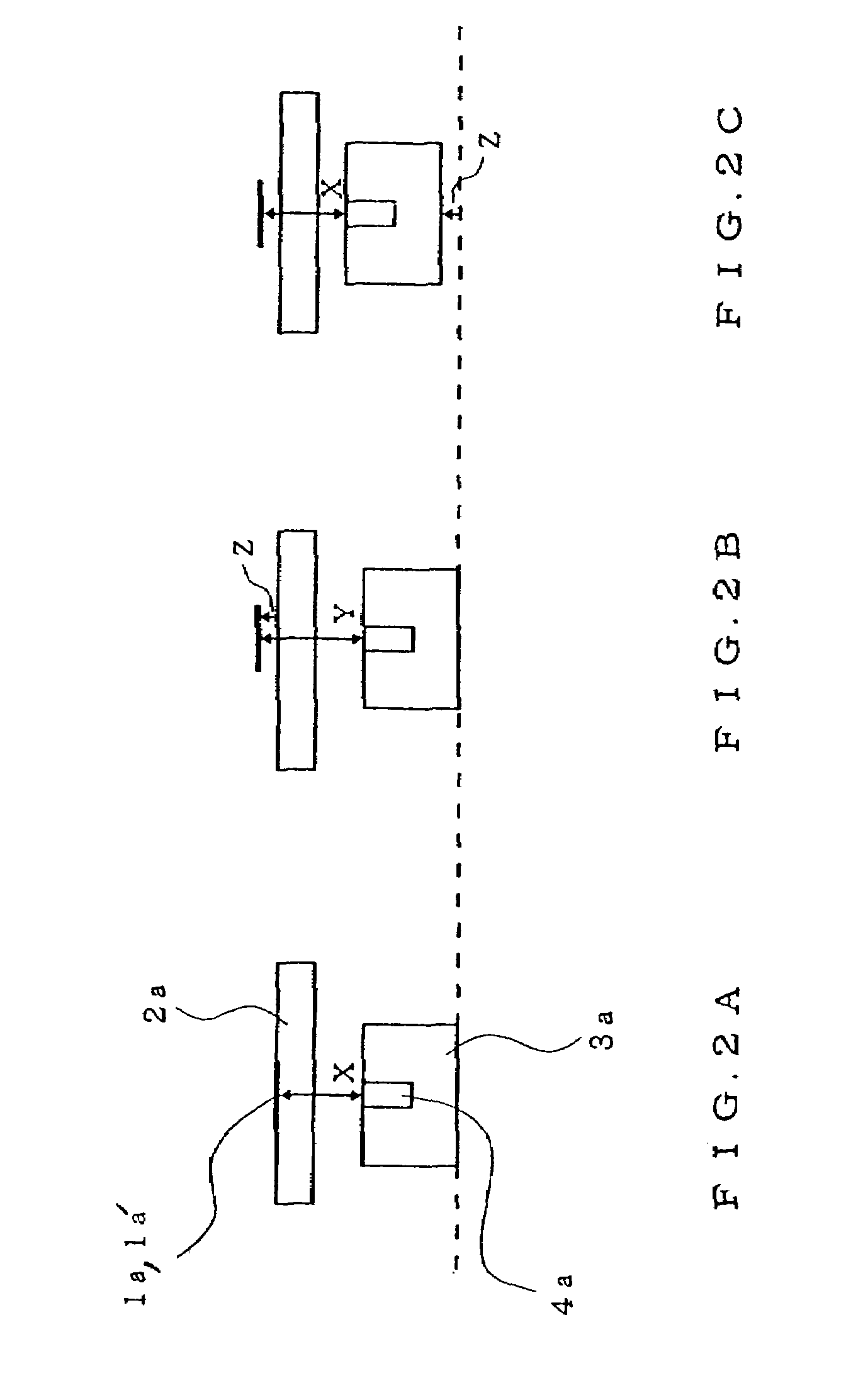
[0090]FIGS. 2A to 2C are schematic diagrams showing relationships between a light transmitting original and a contact image sensor (CIS) unit in a CIS-type image reading apparatus in the present invention.
[0091]Referring to FIG. 2A, an original surface of a light transmitting original la is adhered to a glass surface of an original base 2a and a lens is focused to the original surface. In this case, symbol X denotes a distance from the original surface to an incident side surface of a rod lens array 4a.
[0092]Referring to FIG. 2B, the original surface is apart from the glass surface of the original base 2a by a distance Z so that the light transmitting original la has a slide frame, and symbol Y denotes a distance from the original surface to the incident side surface of the rod lens array 4a. In this case, an equality of (Y=X+Z) is established.
[0093]As described above, in the CIS-type image re...
second embodiment
[0111]Next, the present invention will be described with reference to the drawings.
[0112]FIG. 9 is a cross-sectional view showing an image reading apparatus according to the second embodiment of the present invention. Referring to FIG. 9, the image reading apparatus comprises a main body 5c and an original cover 11a which can openably and closably be supported to the main body 5c. The main body 5c comprises a contact image sensor unit 3c which is longitudinal in a main scanning direction, and a guide rail 8d for guiding the contact image sensor unit 3c in a sub-scanning direction (perpendicular to the main scanning direction). The top of the main body 5c comprises an original base 2c made of a glass plate. The contact image sensor unit 3c provided in the proximity of the glass plate of the original base 2c, comprises therein a line sensor for receiving transmission light from a light transmitting original 1b and a magnet 12a at both ends in the longitudinal direction thereof.
[0113]T...
third embodiment
[0156]Next, the present invention will be described with reference to the drawings.
[0157]FIGS. 17A to 17F are diagrams showing an image reading apparatus of a contact image sensor unit type for reading the image of the light transmitting original and the sheet original, according to the third embodiment of the present invention.
[0158]FIG. 17A is a plan view of the image reading apparatus for reading images of the light transmitting original and the sheet original when an original cover is opened, FIG. 17B is a side view of the image reading apparatus when the original cover is opened, FIG. 17C is a cross-sectional view of the image reading apparatus along an A–A′ line of FIG. 17A, FIG. 17D is a plan view of the image reading apparatus when the original cover is closed, FIG. 17E is a side view of the image reading apparatus when the original cover is closed, and FIG. 17F is a cross-sectional view of the image reading apparatus along a B–B′ line of FIG. 17D.
[0159]Referring to FIGS. 17...
PUM
 Abstract
Description
Claims
Application Information
 - R&D
- Intellectual Property
- Life Sciences
- Materials
- Tech Scout
- Unparalleled Data Quality
- Higher Quality Content
- 60% Fewer Hallucinations
Browse by: Latest US Patents, China's latest patents, Technical Efficacy Thesaurus, Application Domain, Technology Topic, Popular Technical Reports.
© 2025 PatSnap. All rights reserved.Legal|Privacy policy|Modern Slavery Act Transparency Statement|Sitemap|About US| Contact US: help@patsnap.com


