One terminal capacitor interface circuit

a capacitor and interface circuit technology, applied in the field of interface circuits, can solve the problems of low frequency noise, inability to easily correct the offset error of the integration amplifier, and the limitation of the circuit topologies that can be used, and achieve the effect of low frequency nois

Active Publication Date: 2007-06-26
ANALOG DEVICES INC
View PDF11 Cites 65 Cited by
  • Summary
  • Abstract
  • Description
  • Claims
  • Application Information

AI Technical Summary

Benefits of technology

[0009]It is a further object of this invention to provide such an improved one terminal capacitor interface circuit which can cancel amplifier offset error and 1 / f low frequency noise.
[0020]In a preferred embodiment the differential integrating amplifier may include a control circuit for controlling the input common mode voltage at the summing nodes to be substantially equal to an applied reference voltage. The differential integrating amplifier may include a control circuit for controlling the output common mode voltage of the amplifier to be substantially equal to an applied reference voltage. The differential integrating amplifier may include a chopper circuit for selectively inverting the inputs and the outputs of the differential integrating amplifier for canceling amplifier offset error and low frequency noise.

Problems solved by technology

This then limits the circuit topologies that can be used.
In all cases the variation in Vy will corrupt the charge being transferred from the sensor to the integrator, and will cause an error in the measurement of the sensor output.
With these single input integration circuits the integration amplifier offset error and 1 / f low frequency noise cannot be easily corrected.

Method used


Image

  • One terminal capacitor interface circuit
  • One terminal capacitor interface circuit
  • One terminal capacitor interface circuit

Examples


Embodiment Construction

[0034]Aside from the preferred embodiment or embodiments disclosed below, this invention is capable of other embodiments and of being practiced or being carried out in various ways. Thus, it is to be understood that the invention is not limited in its application to the details of construction and the arrangements of components set forth in the following description or illustrated in the drawings. If only one embodiment is described herein, the claims hereof are not to be limited to that embodiment. Moreover, the claims hereof are not to be read restrictively unless there is clear and convincing evidence manifesting a certain exclusion, restriction, or disclaimer.

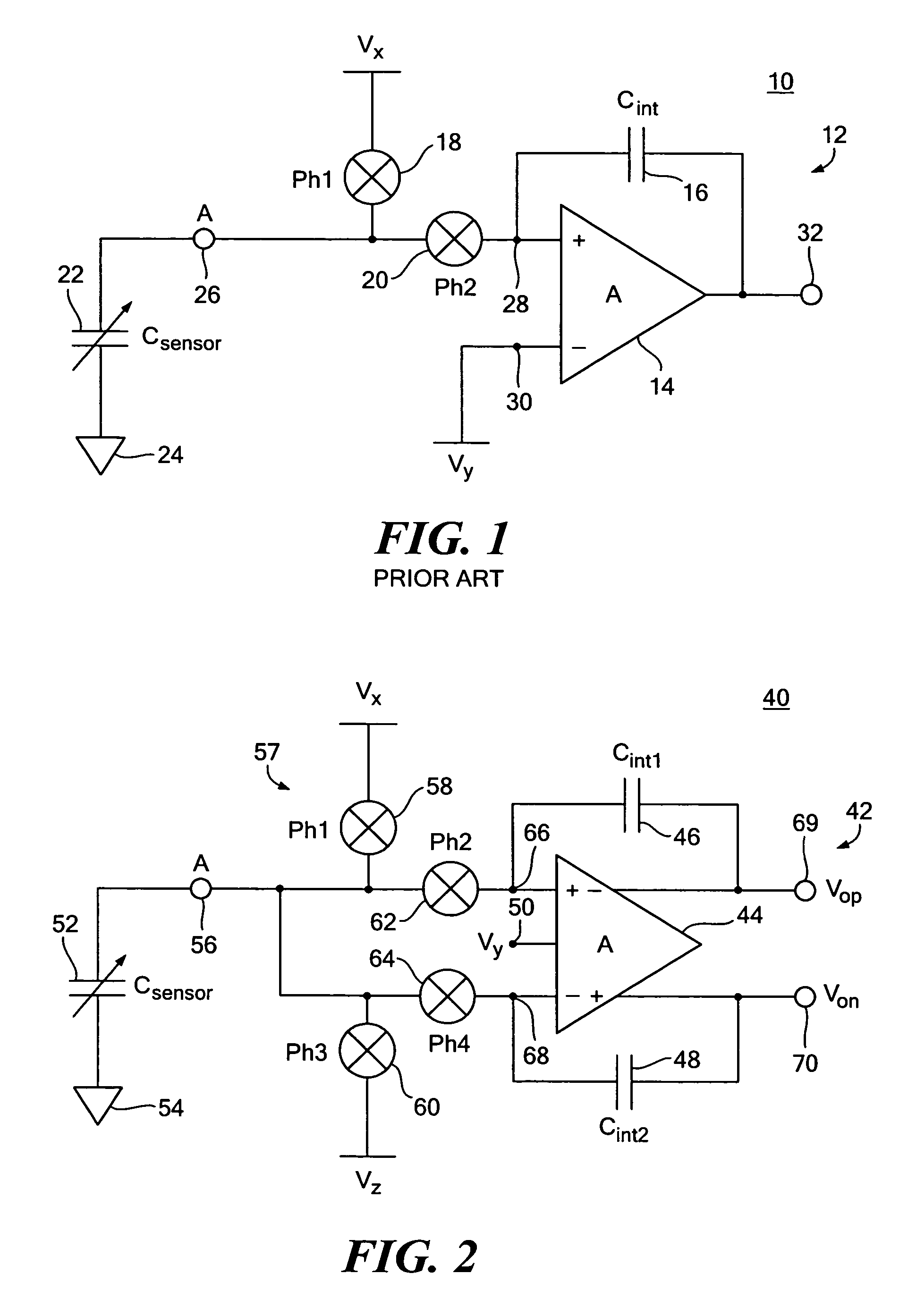
[0035]There is shown in FIG. 1, a conventional prior art one terminal capacitor interface circuit 10 which includes an integrating amplifier 12 including amplifier 14 with feedback or integrating capacitor Cint 16. Also included in interface circuit 10 are phased switches 18 and 20. The capacitor 22 whose capacitance is to ...


PUM


Abstract

A one terminal capacitor interface circuit for sensing the capacitance of a capacitor includes a differential integrating amplifier having an input common mode voltage and two summing nodes whose voltage is substantially equal to the input common mode voltage, a switching circuit for charging the capacitor to a first voltage level in a first phase, connecting, in a second phase, the capacitor to one of the summing nodes of the differential amplifier to provide a first output change substantially representative of the difference between the first voltage level and the input common mode voltage, and also representative of the capacitor; charging the capacitor to a second voltage level in a third phase, and connecting, in a fourth phase, the capacitor to the other summing node of the differential amplifier to provide a second output change substantially representative of the difference between the second voltage level and the input common mode voltage, and also representative of the capacitor; the combined first and second output changes representing the capacitance of the capacitor substantially independent of the input common mode voltage.

Description

RELATED APPLICATIONS[0001]This application claims the benefit of U.S. Provisional Application No. 60 / 660,415 filed Mar. 9, 2005, incorporated by reference herein.FIELD OF THE INVENTION[0002]This invention relates to an interface circuit for sensing capacitance of a one terminal capacitance, and more particularly to such an interface circuit useful in sigma delta modulators and converters and charge amplifiers or capacitance to voltage converters.BACKGROUND OF THE INVENTION[0003]A large number of sensors are capacitive—the physical effect being measured is translated into a change in capacitance which can then be measured electrically. In many cases the two terminals of the sensor capacitor are floating, that is, neither are at a fixed potential. This is very convenient when interfacing the sensor to a measurement circuit, as there is no restriction on the circuit topology. A typical interface circuit will apply an excitation to one terminal of the capacitor, and extract the sensor s...

Claims


Application Information

Patent Timeline
Patent Type & Authority Patents(United States)
IPC IPC(8): G01R27/26H03M3/00
CPCG01D5/24G01P15/125H03M3/34H03M3/458
Inventor O'DOWD, JOHNMCCARTNEY, DAMIENBANARIE, GABRIEL
Owner ANALOG DEVICES INC
Why Eureka
Try Eureka