Slip ring laser illuminator for speed domes

a laser illumination and speed dome technology, applied in the field of surveillance cameras, can solve the problems of mass heat sinking, large 20 watt laser (equivalent to 1000 leds), and large weight of laser equipment in itsel

Active Publication Date: 2007-06-26
BOSCH SECURITY SYST INC
View PDF13 Cites 12 Cited by
  • Summary
  • Abstract
  • Description
  • Claims
  • Application Information

AI Technical Summary

Benefits of technology

[0013]The key innovation in the present invention is the extraordinary weight saving of having only a laser beam delivered over an optical slip joint, rather than power for a laser. The weight and space used by a powerful laser's massive heat-sink and power supply are thereby removed from the dome, allowing for a higher speed of orientation of the camera. For example, a large 20 Watt laser (equivalent to 1000 LEDs) is far too heavy to use inside current speed domes. The laser equipment is bulky in itself and moreover requires massive heat-sinking in order to maintain the equipment within the correct range of operating temperature. However all of the powerful laser's illumination can be delivered out of the end of a 1 millimeter diameter, 4 meter long, flexible, fibre optic tube that is cool to the touch. The emitted light can then be passed through a dispersing lens mounted on the same carriage as the camera in a speed dome. A curved pipe or bent lamp-post style pole can contain the flexible fibre optic tube and confine its curvature between the remote laser and the laser beam outlet adjacent to and aligned with a surveillance camera.
[0018]The optical slip ring can optionally be surrounded by concentric multiple channel electrical slip rings to provide low level power for the video signal and for the camera itself. The electrical slip ring can also be called an electrical rotary connector, electric swivel or electrical rotary joint. It is an electromechanical device that facilitates the transmission of power and electrical signals from a stationary object to a rotating one. An electrical rotary connector can be used in any electromechanical system that requires unrestrained, intermittent or continuous rotation while transmitting power and / or data. Electrical slip rings typically have a series of bushes in contact with corresponding rotating rings. The video signal can be converted from light to electrical information within the camera and then passed over a channel of the electrical slip joint with less weight advantage than with the laser beam optical slip joint, compared to passing the light gathered by a lens over an optical slip joint of fibre optics. It is possible however to separate even the light gathering into a second channel of the fibre optic slip joint, for maximum weight savings within the rotating parts of the speed dome. Without such slip rings, a fibre optic or an electrical cord mounted within an axle of rotation could be twisted rotationally up to a point, but if the rotation continues rather than being reversed, the cord would eventually tighten, knot up, break, or stall the system.
[0022]In order to solve the problem of internal reflection within the dome, that is, light from the illuminator reflecting off the inside of the dome and entering the camera lens, the laser output is pulsed and the camera is synchronized such that it does not collect light just after each pulse, where it is reflected off the inside of the dome, but instead has a delay built in such that only light that has passed through the dome and is returning from the scene of the surveillance is collected by the camera. This is feasible despite the speed of light and the relatively small distances of typical surveillance because modern timing apparatus is capable of nanosecond adjustments.
[0030]8. the laser beam is pulsed and the surveillance camera is synchronized such that it does not collect light until just after the time required for each pulse of the laser beam to be emitted from the fibre optic cable outlet and to bounce back to the camera from an inside surface of the speed dome, but does collect light thereafter until the time required for the laser beam to be reflected from a target area back to the surveillance camera, each laser pulse having a duration that is less than the time it takes light to travel from an outer surface of the speed dome to a target area and back to the surveillance camera, in order that returning light during a camera light-collection phase will not overlap within the speed dome with light reflected from the inside surface of the speed dome from an end portion of the laser pulse emitted from the fibre optic cable outlet;

Problems solved by technology

For example, a large 20 Watt laser (equivalent to 1000 LEDs) is far too heavy to use inside current speed domes.
The laser equipment is bulky in itself and moreover requires massive heat-sinking in order to maintain the equipment within the correct range of operating temperature.

Method used


Image

  • Slip ring laser illuminator for speed domes
  • Slip ring laser illuminator for speed domes
  • Slip ring laser illuminator for speed domes

Examples


Embodiment Construction

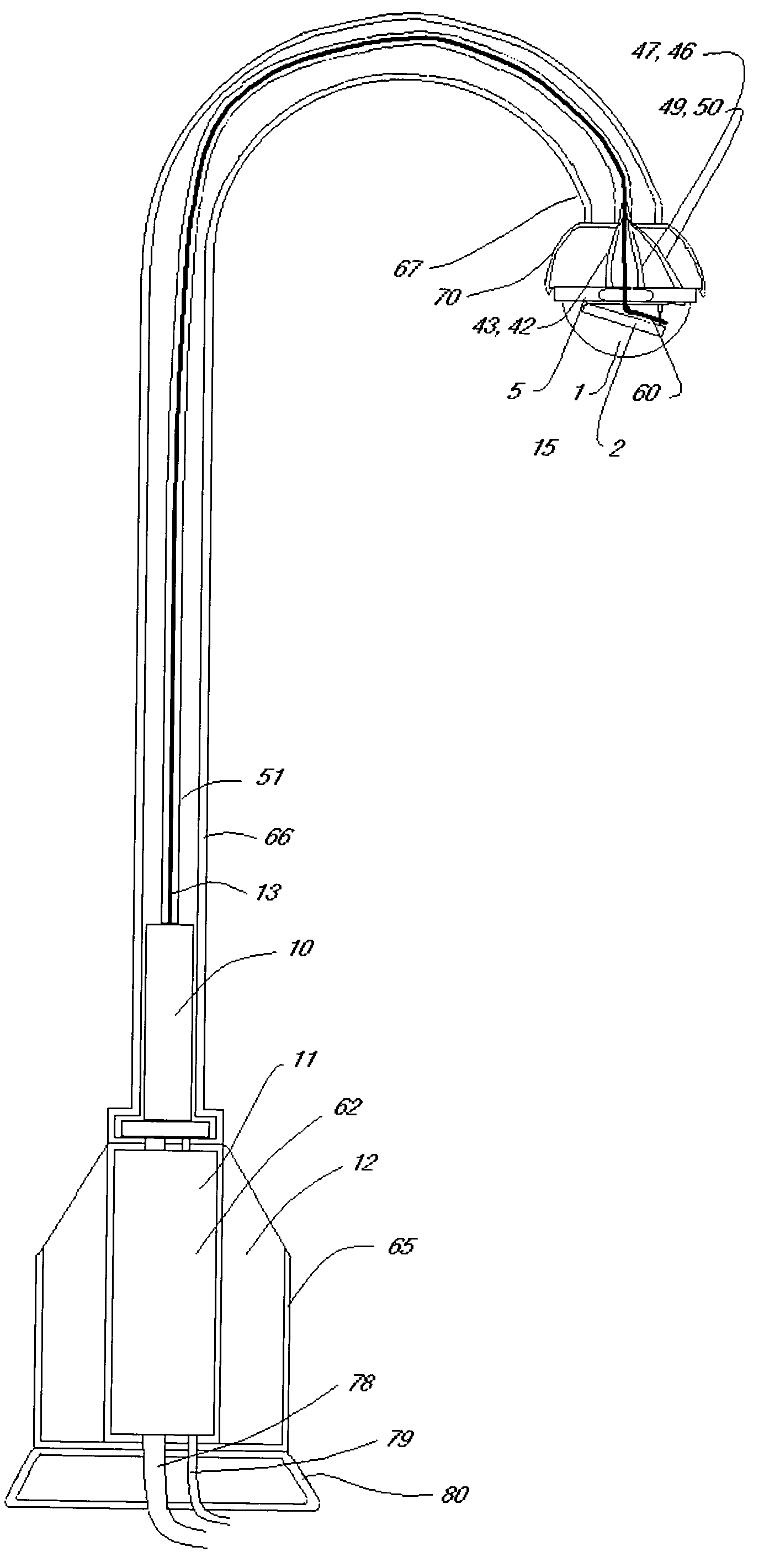
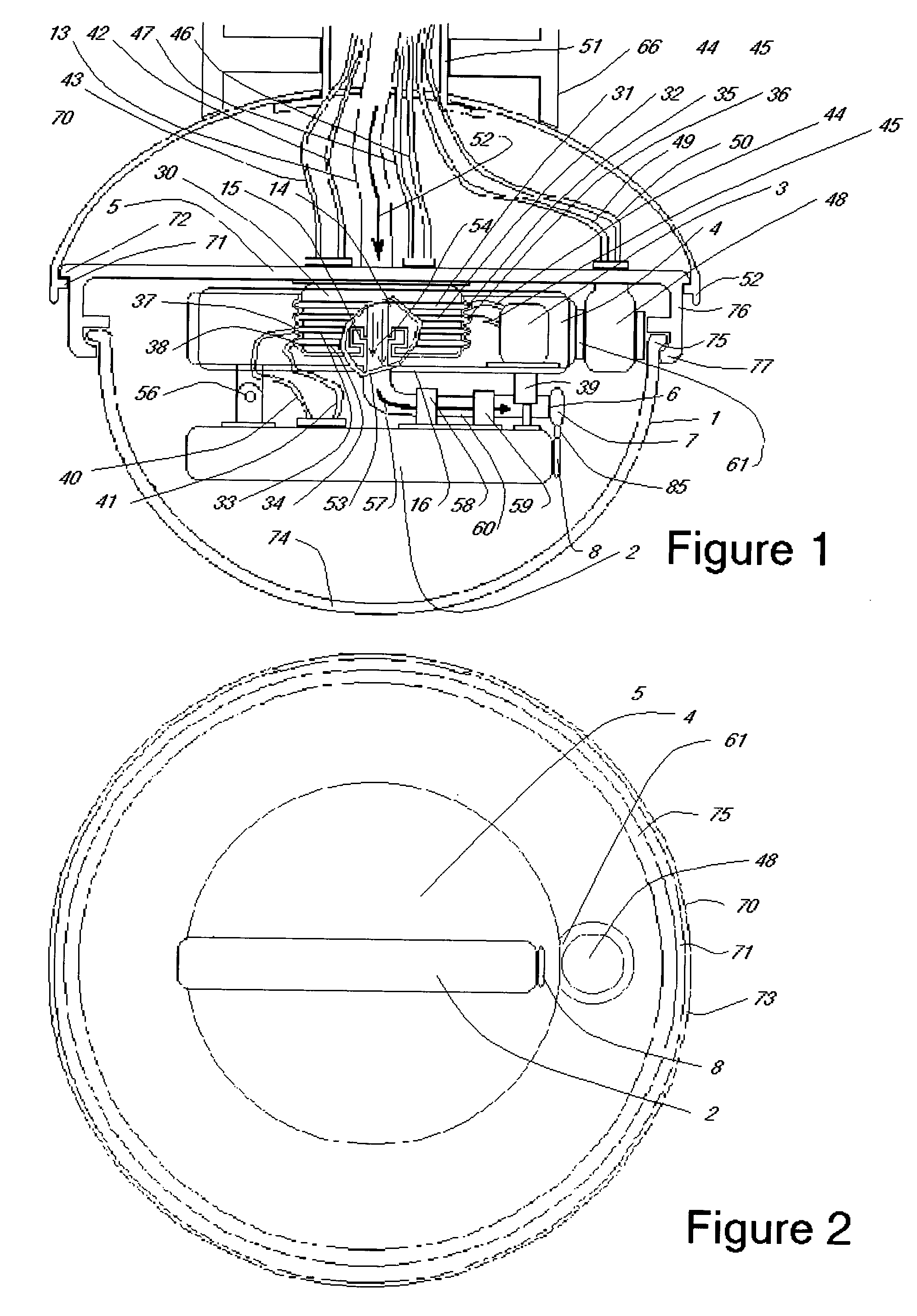
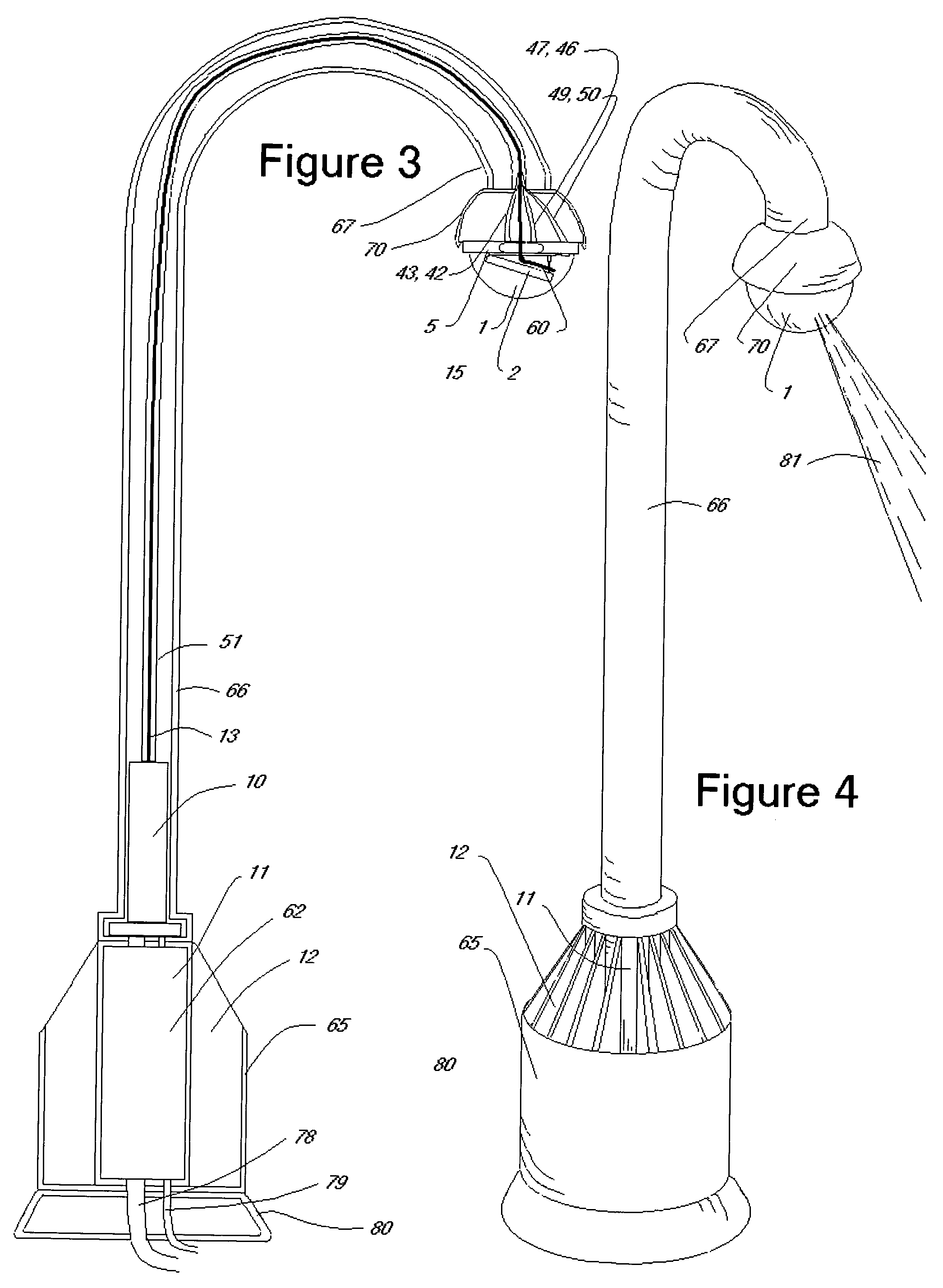
[0038]Referring to FIGS. 1, 2 and 3, the speed dome 1 has a zoom camera 2 mounted to a pan and tilt mechanism comprising motor 3, extender 39 and pivot hinge 56, all in turn mounted on a carriage 4 that is rapidly rotatable with respect to a dome base 5 and therefore rotatable with respect to a surface on which the speed dome base 5 may be mounted. The fibre optic tube outlet 6 is mounted to the camera 2 such that laser light emitted from the fibre optic tube outlet 6 is aligned with the direction in which the zoom camera 2 is pointed. A remote laser 10 with power source 11 and heat-sink 12 is mounted outside the speed dome 1. A main fibre optic tube 13 connects the laser output to the input side 14 of the optical slip ring 15. The output side 16 of the optical slip ring 15 receives the laser output and passes it to the fibre optic tube outlet 6. The input side 14 of the optical slip ring 15 is rotatable with respect to the output side 16 of the optical slip ring 15, though passing ...


PUM


Abstract

An illumination system is provided to enable speed dome camera systems with a minimum of weight increase and existing motor designs to be used in conditions where the ambient illumination is insufficient for surveillance needs. A laser illumination system is divided and dispersed in the system, with its heavy components, namely the power supply, heat sinks, and laser beam generator mounted outside the speed dome and only a lightweight fiber optic cable output mounted adjacent to the speed dome camera. The key innovation in the present invention is having only a laser beam delivered over an optical slip joint rather than power for a laser, allowing for a higher speed of orientation of the camera. A pulsing system is used to avoid flashback within the speed dome.

Description

FIELD OF THE INVENTION[0001]This invention relates to surveillance cameras placed inside protective domes and having advanced pan, tilt, zoom, rotation and illumination features.DESCRIPTION OF THE PRIOR TECHNOLOGY[0002]A significant and increasing percentage of the CCTV market is taken up by speed dome cameras.[0003]Ordinary dome cameras, which are CCTV cameras underneath a dome-shaped housing, typically provide no pan, tilt, zoom or rotation functions. Those features are usually provided in conventional surveillance systems, where a flat top motor is provided upon which is mounted a large bracket, upon which is mounted a camera housing and illuminators each side. Speed dome cameras on the other hand are characterized by speedy pan, tilt, zoom and rotational orienting of the camera within a dome-shaped protective shield.[0004]A typical set of specifications for a speed dome cameras would include for include a ¼-inch color CCD, a 48 dB S / N ratio, 64 preset positions and 480 TV lines....

Claims


Application Information

Patent Timeline
Patent Type & Authority Patents(United States)
IPC IPC(8): H04N5/225G03B15/03H04N5/222
CPCH04N5/2256H04N23/56
Inventor VERNON, MARK WILLIAM
Owner BOSCH SECURITY SYST INC
Why Eureka
Try Eureka