

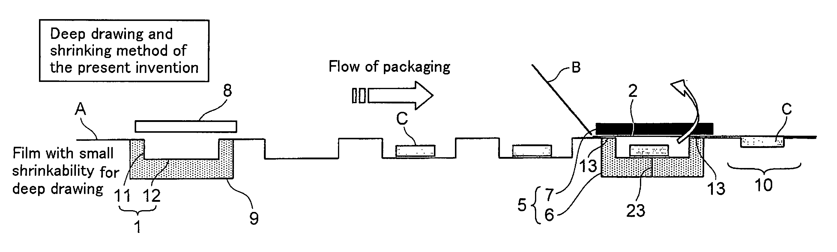
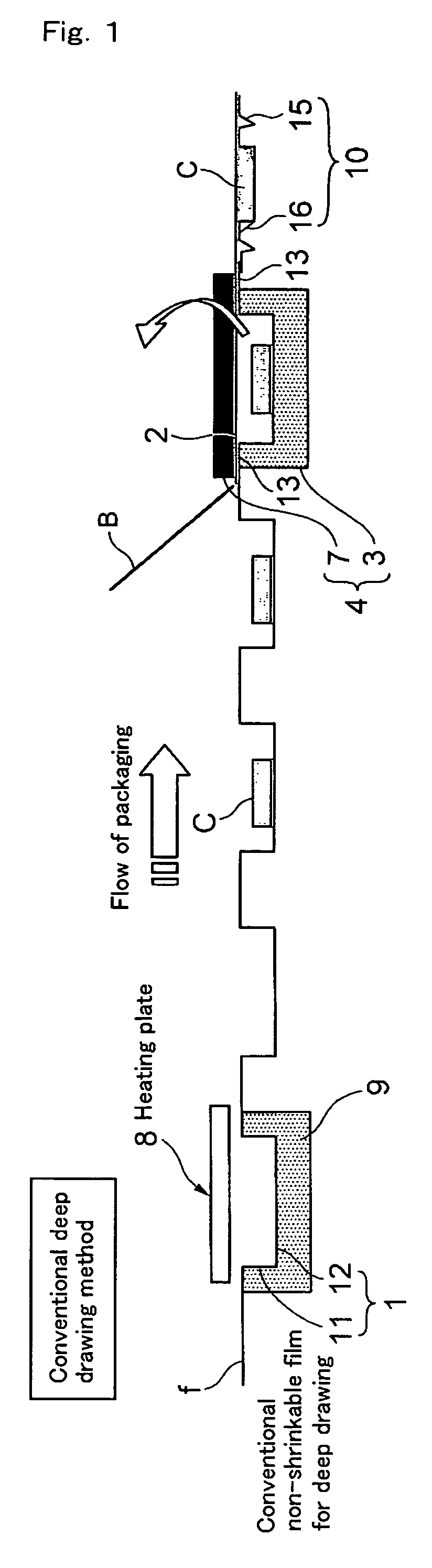
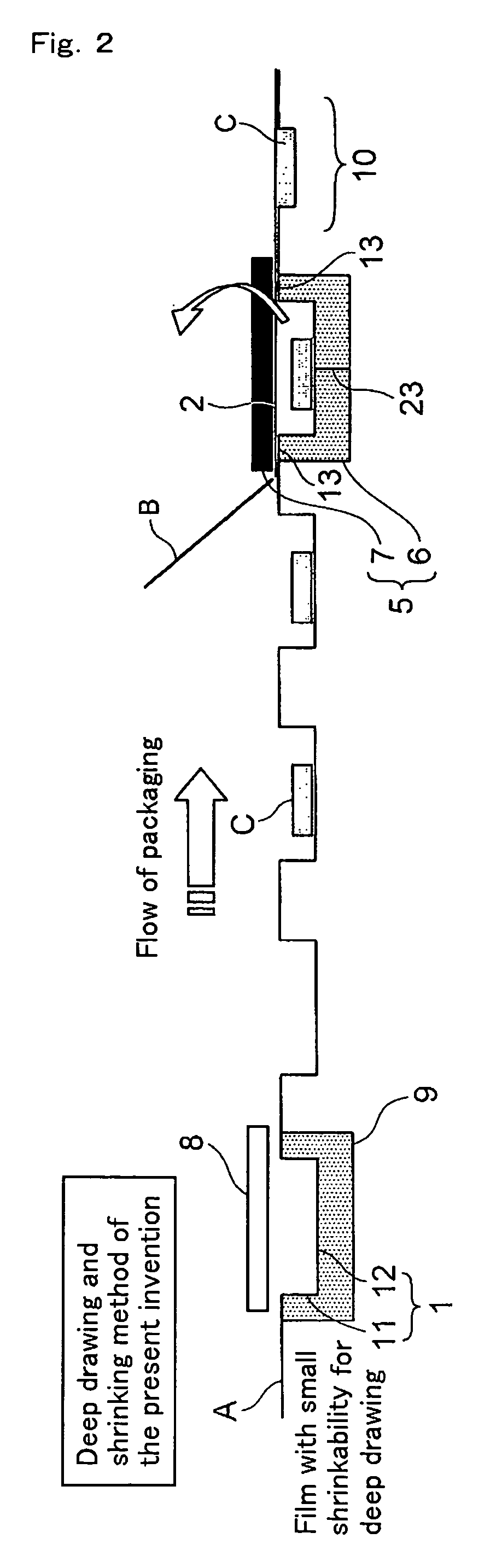
Deep draw packing method and film with small shrinkability for deep draw packing
a deep draw and packing method technology, applied in the field of deep draw packaging methods, can solve the problems of increasing quality-related problems, affecting the quality of packaged products, and affecting the quality of packaged products, and achieve the effect of small shrinkag
- Summary
- Abstract
- Description
- Claims
- Application Information
AI Technical Summary
Benefits of technology
Problems solved by technology
Method used
Image

Examples
examples
[0143]The present invention will next be described in more detail by way of Examples, which should not be construed as limiting the invention thereto.
[0144]The method for measuring physical property described herein is as follows.
Measurement Method for Heat Shrinkage Rate
[0145]A 3 mm-thick corrugated paper sheet is placed on a net rack of a Geer oven (model: MOG-600, a product of Robert CO. Ltd.), and the oven is heated to a predetermined temperature. A film sample on which marks have been provided at an interval (distance) of 10 cm in a machine direction (longitudinal direction, MD) or in a direction (transverse direction, TD) perpendicular to the machine direction of the sample is placed in the heated oven. In this case, the door of the oven is closed immediately after the sample is placed therein so that the door opening period is restricted to three seconds or less. After the oven door is closed and the sample is allowed to stand in the oven for 30 seconds, the sample is removed...
PUM
| Property | Measurement | Unit |
|---|---|---|
| shrinkage rate | aaaaa | aaaaa |
| residual heat shrinkage rate | aaaaa | aaaaa |
| temperature | aaaaa | aaaaa |
Abstract
Description
Claims
Application Information