
Apparatus and method for measuring viscosity

a viscosity and apparatus technology, applied in the direction of direct flow property measurement, instruments, measurement devices, etc., can solve the problems of affecting the viscosity of oil, affecting the viscosity, and affecting the viscosity, so as to achieve high viscosity, reduce test cycle time, and facilitate the effect of viscosity measuremen

Active Publication Date: 2007-07-03
SPECTRO SCI INC
View PDF18 Cites 4 Cited by
  • Summary
  • Abstract
  • Description
  • Claims
  • Application Information

AI Technical Summary

Benefits of technology

This solution enables accurate viscosity measurement of a wider range of oils, reduces clogging issues, and provides more practical test-cycle times, while eliminating the need for adjustments or modifications, and avoids the limitations of optical sensors by using pressure sensors for fluid flow detection.

Problems solved by technology

Under normal service, oil will degrade, adversely affecting its viscosity due to factors such as oxidation, nitration, and particulate contamination.
Even under normal operating conditions, viscosity can degrade at a rapid pace.
The result of viscosity degradation is often excessive motor wear and damage.
However, used oil can be difficult to properly monitor.
Typical oil borne contaminants such as wear metals, soot, particulates, glycol and water can cause a conventional viscometer to clog or jam.
This can result in erroneous viscosity readings.
In addition, thick, opaque motor oil is often not compatible with the optical sensors used to monitor the flow of a sample in conventional automated equipment.
A residue of oil can cover such sensors and result in a false signal.
Since an essential part of such a test is determining the time required to empty the fluid reservoir, conventional viscometers are problematic when measuring used oil samples.

Method used


Image

  • Apparatus and method for measuring viscosity
  • Apparatus and method for measuring viscosity
  • Apparatus and method for measuring viscosity

Examples


Embodiment Construction

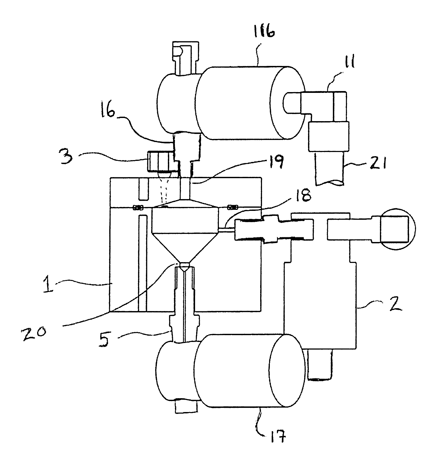
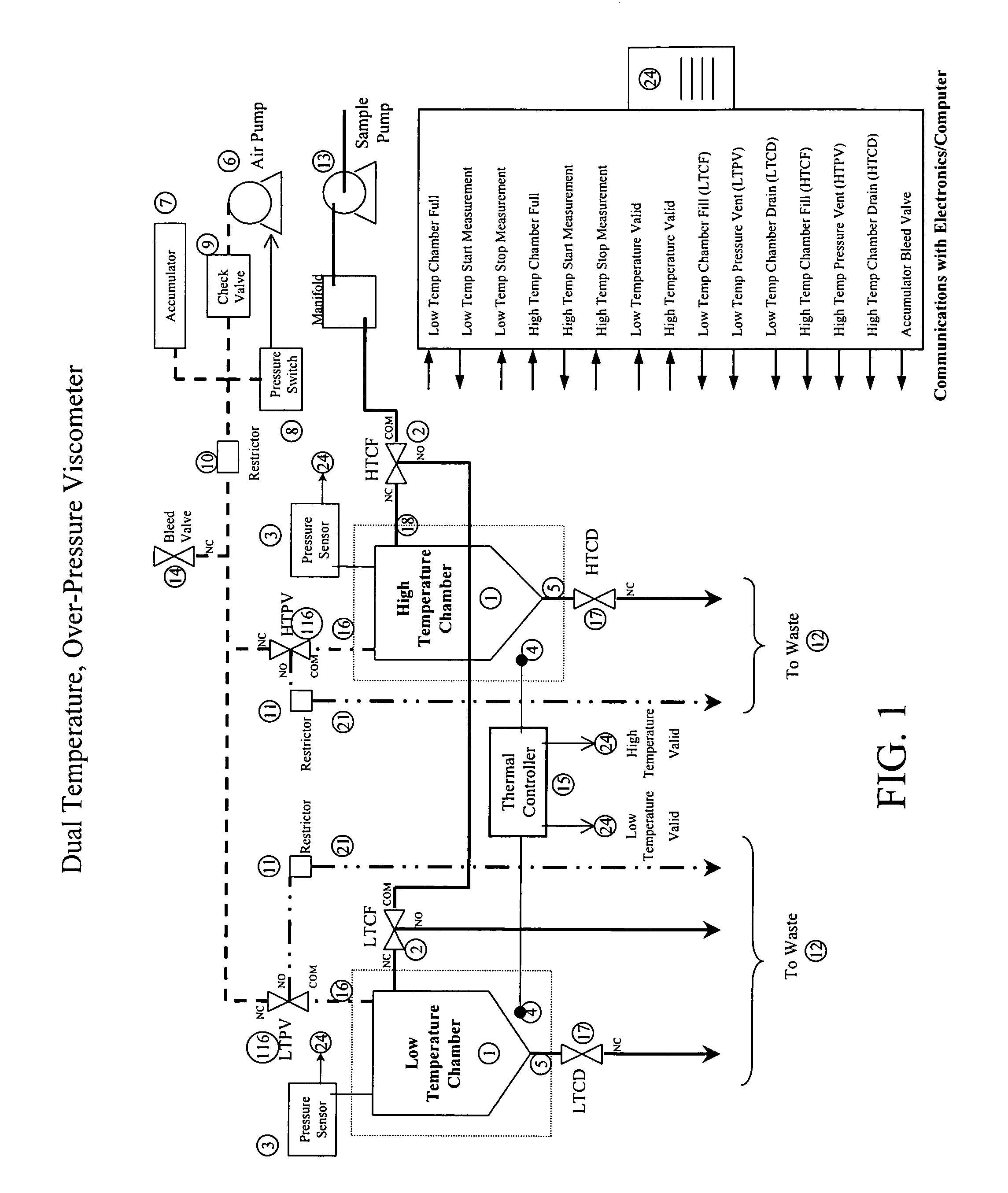
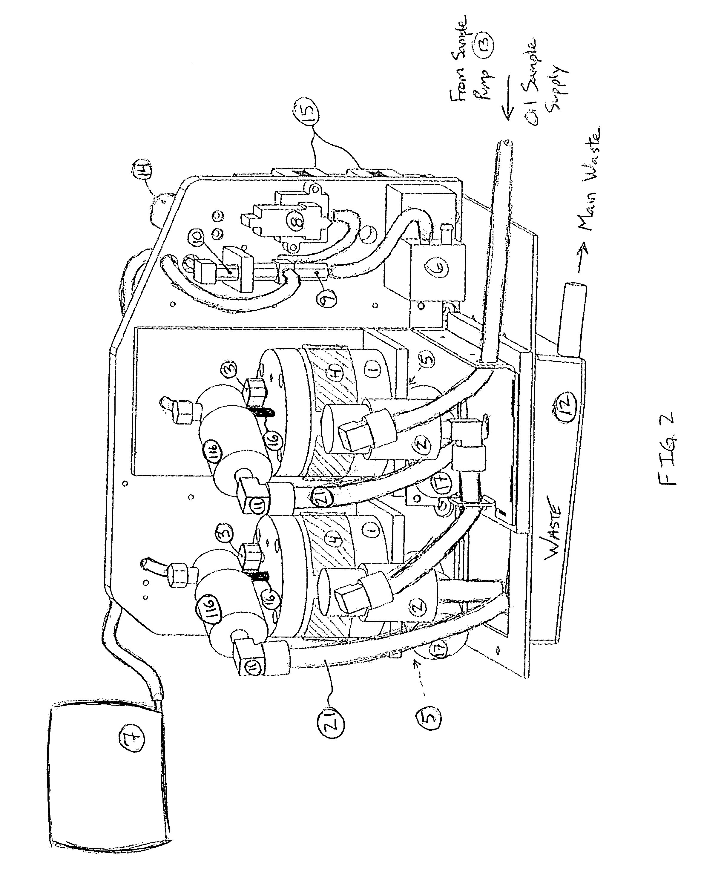
[0018]The present invention provides methods and apparatus for the measurement of viscosity in a sample, preferably, a sample of a petroleum product. In one aspect, disclosed herein, is a viscometer having a sample reservoir for receiving a sample and a source of pressurized gas for creating an over-pressure condition in the sample reservoir. When a sample is delivered to the sample reservoir, the pressurized gas can be fed to the sample chamber to force a sample through a passageway, and thereby prevent clogging and / or move a thick sample through the viscometer.

[0019]To determine viscosity, the time required to empty the sample reservoir is calculated. Unlike conventional viscometers that use optical sensors, the viscometer disclosed herein senses changes in pressure to monitor sample flow. In one aspect, pressure data is used to determine the amount of time required to empty the sample reservoir of a sample. The length of time can then be used to calculate the viscosity of the liq...


PUM

PropertyMeasurementUnit
temperaturesaaaaaaaaaa
pressureaaaaaaaaaa

Abstract

An apparatus and methods for analysis of a petroleum product, specifically determining the viscosity of a sample, are disclose. The apparatus includes a sample reservoir for receiving a liquid sample and a pressure regulator for applying hyperbaric pressure to a sample within the reservoir. When pressure is applied to the sample reservoir, the sample is forced through a passageway and a pressure sensor monitors the pressure in the sample reservoir. A drop in the pressure can be used to determine when the reservoir is empty and sample viscosity can be calculated based on the time required to empty the reservoir.

Description

BACKGROUND OF THE INVENTION[0001]Proper viscosity is of critical importance for petroleum based oils to work effectively, whether the oils is used for lubrication, or otherwise. Under normal service, oil will degrade, adversely affecting its viscosity due to factors such as oxidation, nitration, and particulate contamination. Even under normal operating conditions, viscosity can degrade at a rapid pace. The result of viscosity degradation is often excessive motor wear and damage. As such, testing the viscosity of oil should be an essential part of any maintenance program.[0002]Many types of viscometers are known in the art. One type is the capillary tube viscometer which consists of a capillary tube and a fluid reservoir that holds a specified volume of sample liquid. The force of gravity produces a hydrostatic head in the reservoir, which causes the liquid to flow through the capillary tube. The time required for a fixed fluid volume to flow through the capillary tube is measured a...

Claims


Application Information

Patent Timeline
Patent Type & Authority Patents(United States)
IPC IPC(8): G01N11/06G01N11/00G01N11/08
CPCG01N11/06G01N33/30G01N2011/002
Inventor ASHER, WILLIAM E.POPE, BRADFORD J.ZHOU, ZHOU
Owner SPECTRO SCI INC
Learn More