Method and apparatus for producing mechanical fibers

a mechanical fiber and mechanical fiber technology, applied in the field of thermomechanical fiber production, can solve the problems of large energy consumption of internal friction in the fiber phase, large energy consumption of the fiber and the segment surface, and the length of the dwell time of the mass in the refiner, so as to improve the quality of the fiber, and improve the effect of suitableness

Inactive Publication Date: 2007-07-03
M REAL OYJ
View PDF13 Cites 8 Cited by
  • Summary
  • Abstract
  • Description
  • Claims
  • Application Information

AI Technical Summary

Benefits of technology

[0013]The invention offers significant benefits.
[0014]The greatest benefit of the invention is decrease in amount of energy required for producing the fibers. Further, the properties of the produced fiber like color and fiber length may change or can be changed by effecting the process conditions according to the invention. Whether this leads to improvement of fiber quality depends on which properties are desired for making the final paper product. Since different kind of products require different properties from the fiber, the fibers made by the invention is better suitable for some products that others and improvement of quality is thus paper grade specific. However, the invention provides enhanced possibilities for controlling the residence time of the fibers and other process parameters whereby the fibers can be made more accurately to specific requirements and the quality is thus increased.
[0015]The average residence time of the fibers in the refiners is shorter than in known systems and peak temperatures are also lowered. Temperature level variations are also smaller. Because of this, danger for darkening of the fibers is smaller and it is possible to produce brighter fibers. The pressure from the previous stage housing to the following stage can be freely chosen to improve the fiber properties. Lower operating pressure reduces stresses of the machinery whereby bearings, frame and other parts of the apparatus can de designed for lower loads. Infeed of water or steam is not needed for regulating the temperature in the refiner and no steam is produced in the refiner.

Problems solved by technology

The collisions between fiber and rotor bar edges and collisions between fibers, friction between fiber and segment surfaces and internal friction in the fiber phase consume a considerable amount of energy.
This kind of process requires large amount of energy for each ton of fibers produced.
If the consistency of the fibers is not right, the dwell time of the mass in the refiner may become longer and the mass may overheat and become dark.

Method used


Image

  • Method and apparatus for producing mechanical fibers
  • Method and apparatus for producing mechanical fibers

Examples


Embodiment Construction

[0017]Objects and features of the invention will become apparent from the following detailed description considered in conjunction with the accompanying drawing. It is to be understood, however, that the drawings are intended solely for purposes of illustration and not as a definition of the limits of the invention, for which reference should be made to the appended claims.

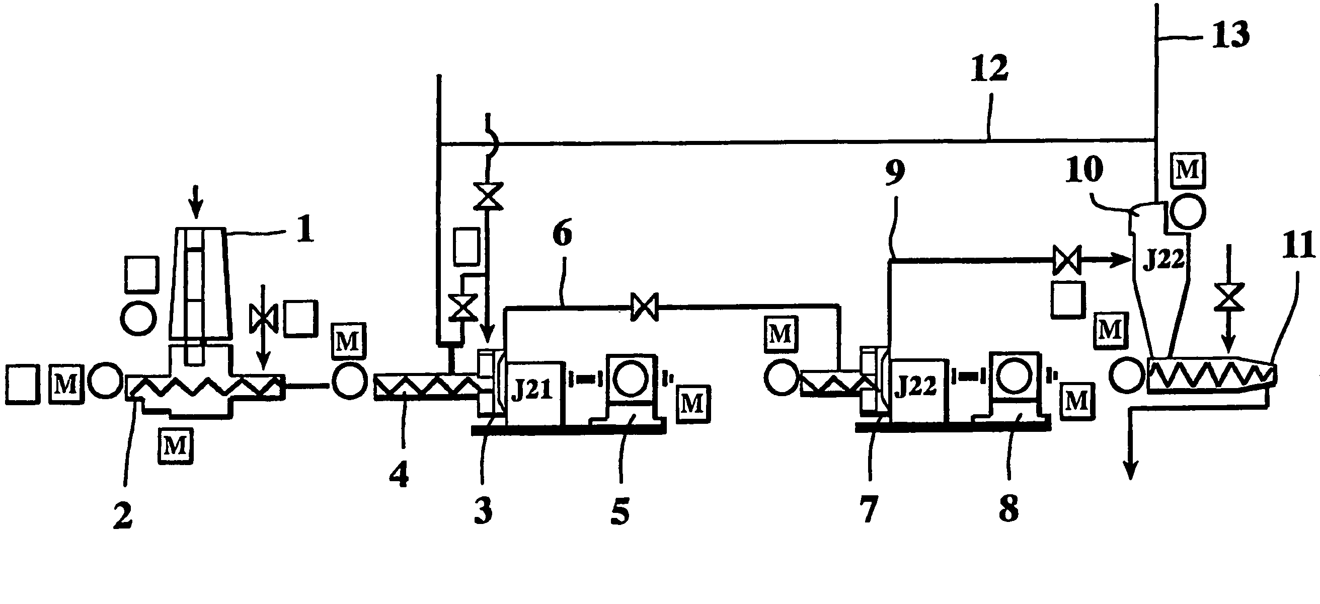
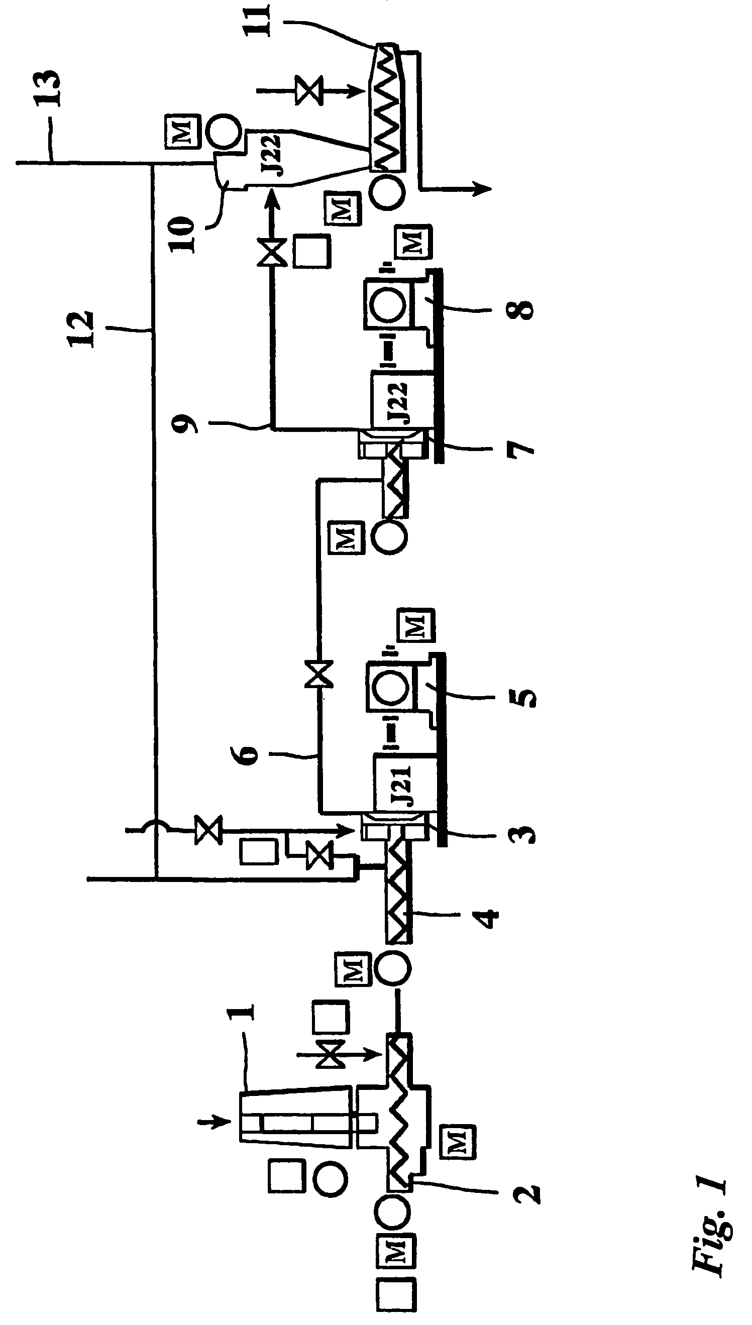
[0018]The drawing shows main parts of a fiber producing line. The first apparatus in the line is a silo 1, into which prefabricated wood chips are fed. At the bottom of the silo 1 is a feeding screw 2 for removing the chips from the silo 1 feeding them further in the line. Next in line is a first refiner 3 into which chips are fed by a second feeding screw 4. The refiner 3 is driven by an electric motor 5 that rotates the rotor of the refiner. The rotor works against a stationery stator and chips that are refined travel in the gap of the stator and the rotor. The rotary force of the rotor pushes the mixture of chi...


PUM

PropertyMeasurementUnit
thermomechanicalaaaaaaaaaa
massaaaaaaaaaa
residence timeaaaaaaaaaa

Abstract

The purpose of this invention is to provide a method and an apparatus for producing thermomechanical fibers using less energy per ton that has previously been required for similar type of production. The invention is based in that at least two refiners are combined so that mixture of chips, water and steam is first fed into a first refiner wherein the chips are broken up and the mass flow from the first refiner is then fed into the second refiner for breaking the fibers to final freeness level. The mass flow of steam and fibers is fed forwards at least in the first refiner by the rotational energy of the refiner rotor so that essentially no flowback of the steam occurs. The mass flow exciting the first refiner is fed completely to the second refiner and no steam is extracted from the mass flow before the second refiner.

Description

[0001]This application is a 371 of international application PCT / FI2003 / 000880, which claims priority based on Finnish patent application No. 20022050 filed Nov. 18, 2002, which is incorporated herein by reference.FIELD OF THE INVENTION[0002]The invention relates to producing thermomechanical fibers by a refining process using at least one refiner.[0003]Invention also relates to an apparatus for implementing the method.BACKGROUND OF THE INVENTION[0004]In the refining process, wood is fed in chip form into a narrow gap between stator and rotor of a refiner together with water. The cross section of the gap narrows from the center of the refiner towards the outer perimeter. The surfaces of the rotor and stator have bars that have edges for breaking the wood material into fibers. The chips are defibrated and fibrillated during their passage through the refiner. Refining can take place in one refiner or it can be continued in subsequent refiners.[0005]The chips are fed into the center of...

Claims


Application Information

Patent Timeline
Patent Type & Authority Patents(United States)
IPC IPC(8): B02C1/00B02C11/08D21B1/12
CPCD21B1/12
Inventor VIKMAN, KAI
Owner M REAL OYJ
Why Eureka
Try Eureka