Short throw projection system and method

a projection system and short throw technology, applied in the field of projection systems and methods, can solve the problems of difficult optical correction of inherent two-dimensional distortions and high cos

Active Publication Date: 2007-07-03
GEO SEMICONDUCTOR INC
View PDF29 Cites 27 Cited by
  • Summary
  • Abstract
  • Description
  • Claims
  • Application Information

AI Technical Summary

Benefits of technology

[0015](d) said electronic correction unit being further adapted to independently pre-distort the geometry of each primary color represented by the input image data and generate a pre-distorted primary color image data to compensate for differences in the optical refraction of each col

Problems solved by technology

These inherent two-dimensional distortions are gene

Method used


Image

  • Short throw projection system and method
  • Short throw projection system and method
  • Short throw projection system and method

Examples


Embodiment Construction

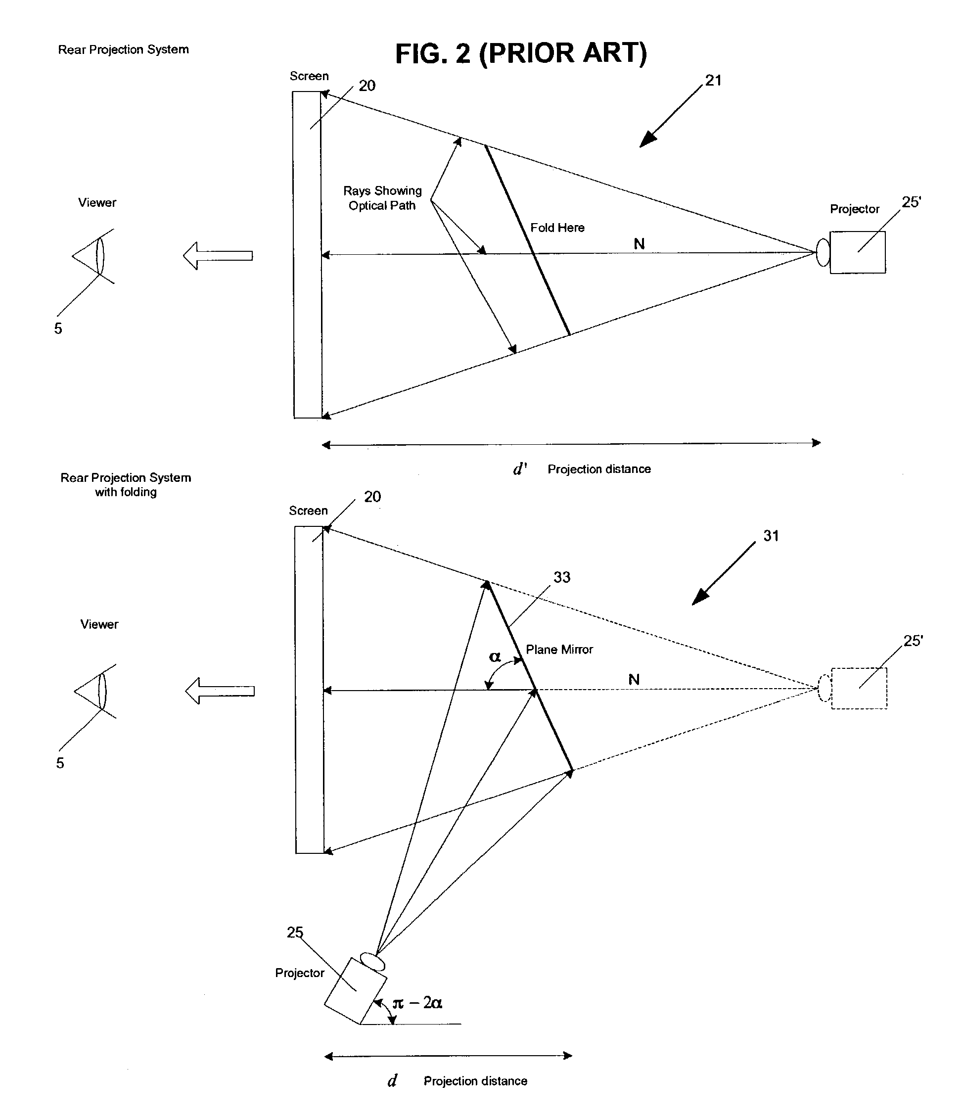
[0037]FIGS. 2 and 3 show typical prior art rear projection systems 21 with conceptual fold(s) and prior art rear projection systems 31 that use optical path folding to reduce the projection distance d and accordingly the throw ratio.

[0038]As shown in FIG. 2, a single fold arrangement is shown where image folding is achieved by using a planar mirror 33 to reflect the light path from projector 25 to screen 20. Specifically, the result of single folding is that projector 25 can be placed in front of plane mirror 33 with the same effect as if projector 25 was positioned as projector 25′. This arrangement results in the reduction of the projection distance (i.e. distance d instead of the distance d′ associated with the non-folded arrangement). As shown, a fold at a distance of d / s from the screen (s>1) will reduce the throw ratio by s. Provided the angles of the mirror(s) and the projector are chosen correctly, the image should be displayed free of any distortions. The single folding arr...


PUM


Abstract

A short throw projection system and method for displaying a corrected optical image on a projection screen based on input image data that includes an electronic correction unit, an image projector and a reflection assembly. The electronic correction unit receives the input image data and generates pre-distorted image data. The image projector receives the pre-distorted image data from the electronic correction unit and projects a pre-distorted optical image that corresponds to the pre-distorted image data or a pre-distorted image compensated by the projection optic distortion. The optical reflection assembly is positioned in the optical path of the pre-distorted optical image to project an optical image on the projection screen. The reflection assembly can consist of various combinations of curved and planar mirrors as desired. The electronic correction unit is encoded to pre-distort the geometry of the image represented by the image data such that when the pre-distorted optical image is projected through the image projector and reflected within the reflection assembly, the optical and geometric distortions associated with the image projector and the mirrors within the reflection assembly are eliminated in the displayed optical image.

Description

[0001]This application claims the benefit under 35 U.S.C. 119(e) of U.S. Provisional Application No. 60 / 387,597, filed Jun. 12, 2002.FIELD OF THE INVENTION[0002]This invention relates to projection systems and methods and more particularly relates to a short throw projection system and method.BACKGROUND OF THE INVENTION[0003]A general projection system may be classified as front projection based or rear projection based depending on the positions of the viewer and projector relative to the screen. In a front projection system, the viewer and projector are on the same side of the screen, with the image from the projector reflecting off the screen to the viewer. In a rear projection system, the projector and viewer are on opposite sides of the screen, with the image from the projector being “transmitted through” the screen to the viewer.[0004]FIG. 1 shows a prior art rear projection system 21 and a prior art front projection system 23. As shown, the image projectors 25 can be placed a...

Claims


Application Information

Patent Timeline
IPC IPC(8): H04N9/28G03B21/14H04N5/74
CPCH04N5/7408H04N9/3141
Inventor BASSI, ZORAWAR S.SMITH, GREGORY LIONELLEE, LOUIE
Owner GEO SEMICONDUCTOR INC
Why Eureka
Try Eureka