Asymmetric, optimized common-source bi-directional amplifier

a bi-directional amplifier and common-source technology, applied in the direction of rf amplifiers, two-way amplifiers, transmission, etc., can solve the problems of low mean time to failure and rework, increased noise figure for the receive mode, and ineffective amplifier approaches, etc., to achieve high power performance, optimize desired performance, and achieve high power amplification

Active Publication Date: 2007-07-03
NORTHROP GRUMMAN SYST CORP
View PDF13 Cites 8 Cited by
  • Summary
  • Abstract
  • Description
  • Claims
  • Application Information

AI Technical Summary

Problems solved by technology

The elimination of separate function blocks decreases the part count and improves yield and reliability because amplifiers with high part counts complicate the manufacturing process and usually lead to a low mean time to failure and rework.
However, the typical integrated amplifier approach is not as effective as individual functional blocks because Radio Frequency (RF) signal routing by RF switches within a single integrated amplifier usually results in increased insertion loss in both the RF transmit and the RF receive paths, causing increased noise figure for the receive mode, and loss in output power and power efficiency in the transmit mode.
All bi-directional amplifiers featuring passive RF switching topologies have disadvantages, including increased insertion loss, resulting in increased noise figure in the receive path and decreased output power in the transmit path.
However, prior art active RF signal steering topologies also have disadvantages which include amplifiers not designed for optimal high power or low noise applications, and amplifiers having pairs of input and output terminals.

Method used


Image

  • Asymmetric, optimized common-source bi-directional amplifier
  • Asymmetric, optimized common-source bi-directional amplifier
  • Asymmetric, optimized common-source bi-directional amplifier

Examples


Embodiment Construction

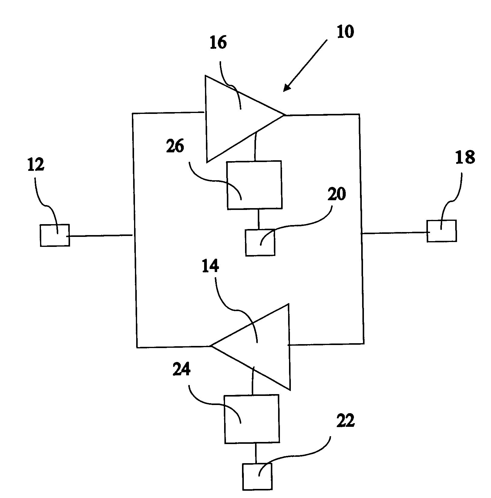
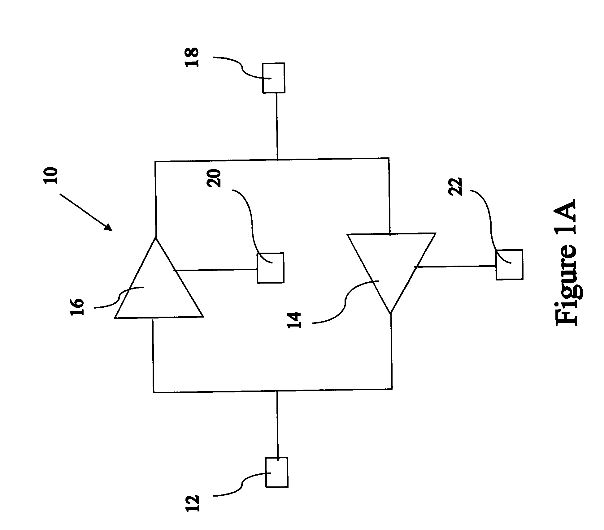
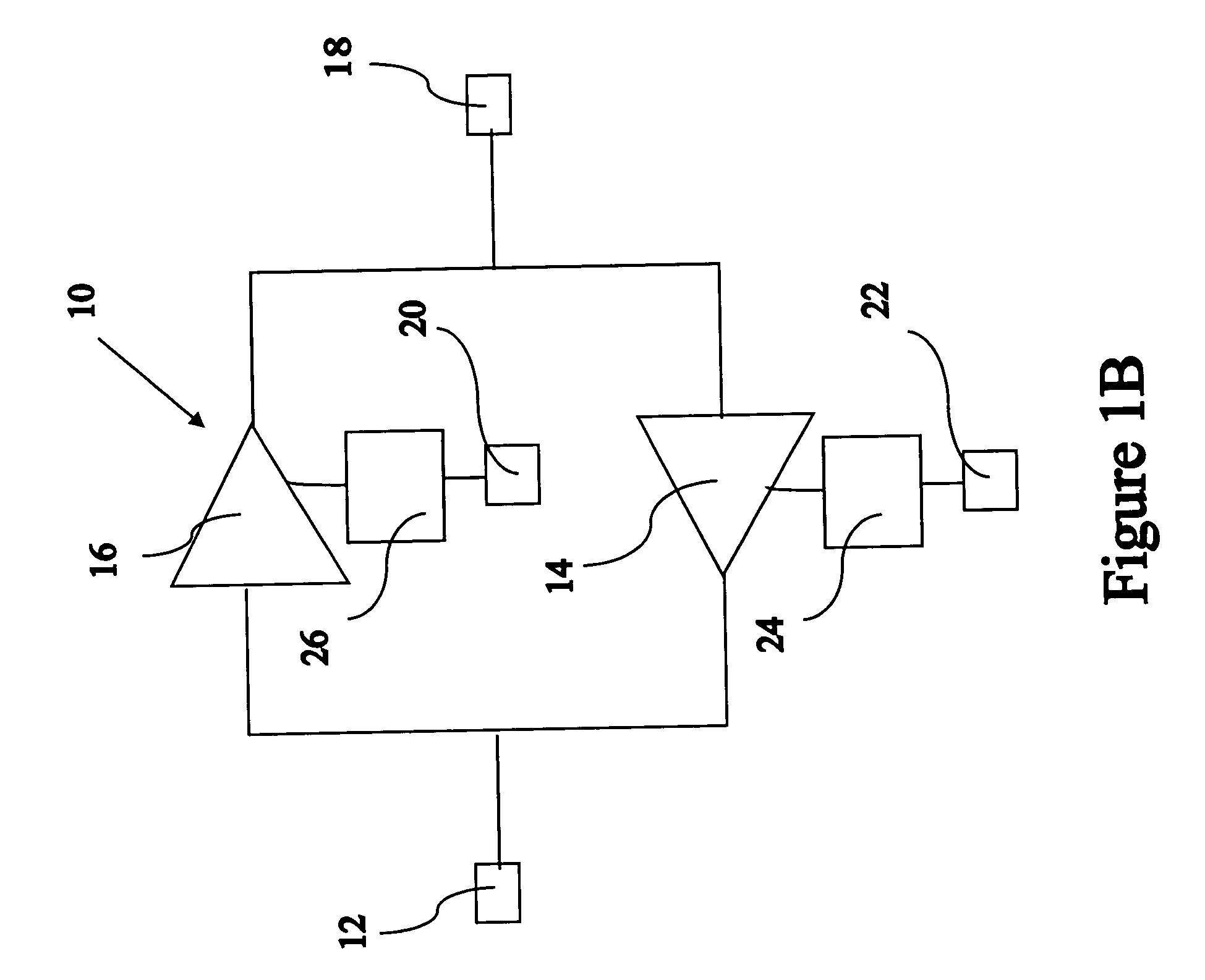
[0021]Referring particularly to FIG. 1A, a block diagram of a bi-directional amplifier 10 of the present invention is shown, which bi-directional amplifier 10 includes a first mode and a second mode. Further, bi-directional amplifier 10 includes a first amplification path and a second amplification path. For purposes of describing the present invention, said first mode is a receive mode, said second mode is a transmit mode, said first amplification path is a receiver amplifier 14, and said second amplification path is a transmitter amplifier 16. Further, it shall be noted that the present invention may include any first amplification path and any second amplification path and should not be limited to receiver amplifier 14 and transmitter amplifier 16.

[0022]In addition, bi-directional amplifier 10 comprises a first port 12, a second port 18, a receiver electrode 22, and a transmitter electrode 20. Receiver electrode 22 and transmitter electrode 20 controls the direction of a signal f...


PUM


Abstract

A common source, bi-directional microwave amplifier is described. More particularly, the present invention is a microwave, common source, bi-directional amplifier that includes a first amplification path and a second amplification path wherein the signal directional flow is controlled through the selective biasing of the first amplification path and the second amplification path. Each amplification path is designed to optimize desired performance. For signal flow through the first amplification path, the first amplification path is biased-on and the second path is biased-off. For signal flow through the second amplification path, the second amplification path is biased-on and the first path is biased-off.

Description

FIELD OF THE INVENTION[0001]The present invention relates to a bi-directional signal flow amplifier for electronic systems. More particularly, the present invention relates to bi-directional signal flow amplifier topology having a high power transmitter amplifier path for a high level transmit signals and a low noise receive amplifier path for a low level receive signal for electronic systems.DESCRIPTION OF THE PRIOR ART[0002]Radio frequency and microwave communication systems receive and transmit signals to and from a multiplicity of clients. Electronic systems require electronic hardware such as amplifiers for various signal applications such as low noise signal operation and / or high output power signal operation. Some examples of electronic systems include radar and communication systems. During low noise signal operation, the amplifier boosts the signal gain of weak, low level signals while minimally increasing the system noise figure. During high power signal operation, the amp...

Claims


Application Information

Patent Timeline
Patent Type & Authority Patents(United States)
IPC IPC(8): H04B1/44H03F3/193H03F3/62H04B1/18H04B1/40
CPCH03F1/56H03F3/193H03F3/62H04B1/44H03F2200/222H03F2200/372H03F2200/387H03F2200/451
Inventor YANG, JEFFREY MING-JERNISHIMOTO, MATTCHUNG, YUN-HOBATTUNG, MICHAELLAI, RICHARD
Owner NORTHROP GRUMMAN SYST CORP
Why Eureka
Try Eureka