Robotic system for optically inspecting workpieces

a robot system and workpiece technology, applied in the direction of total factory control, programme control, instruments, etc., can solve the problems of production time waste and more than compensating the waste of this procedure, and achieve the effect of facilitating replacement and minimal loss

Inactive Publication Date: 2007-07-03
WD MEDIA
View PDF11 Cites 69 Cited by
  • Summary
  • Abstract
  • Description
  • Claims
  • Application Information

AI Technical Summary

Benefits of technology

[0014]In one embodiment, the third receptacle is in a drawer which can be removed from the cell without having to open the safety enclosure. This facilitates replacing the third receptacle without shutting down the cell.

Problems solved by technology

This wastes production time.
Although workpieces that would otherwise be re-worked or evaluated further are placed in the reject receptacle, the waste incurred by this procedure is more than compensated for by the fact that it is unnecessary to shut the cell down and remove the safety enclosure when the third receptacle is full.

Method used


Image

  • Robotic system for optically inspecting workpieces
  • Robotic system for optically inspecting workpieces
  • Robotic system for optically inspecting workpieces

Examples


Embodiment Construction

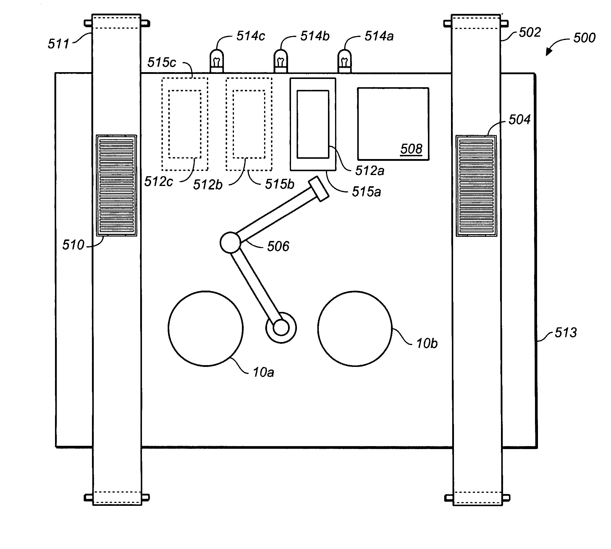
[0040]This specification includes a description of an optical tester (comprising one or more test heads) that can be used in conjunction with a test cell constructed in accordance with the invention. The cell itself is discussed in section XII below. It is emphasized that the cell of the present invention can be used with different types of testers, e.g. the heads described in the above-incorporated Treves patents or magnetic testers (described below).

I. Overview of Optical Inspection Apparatus 10

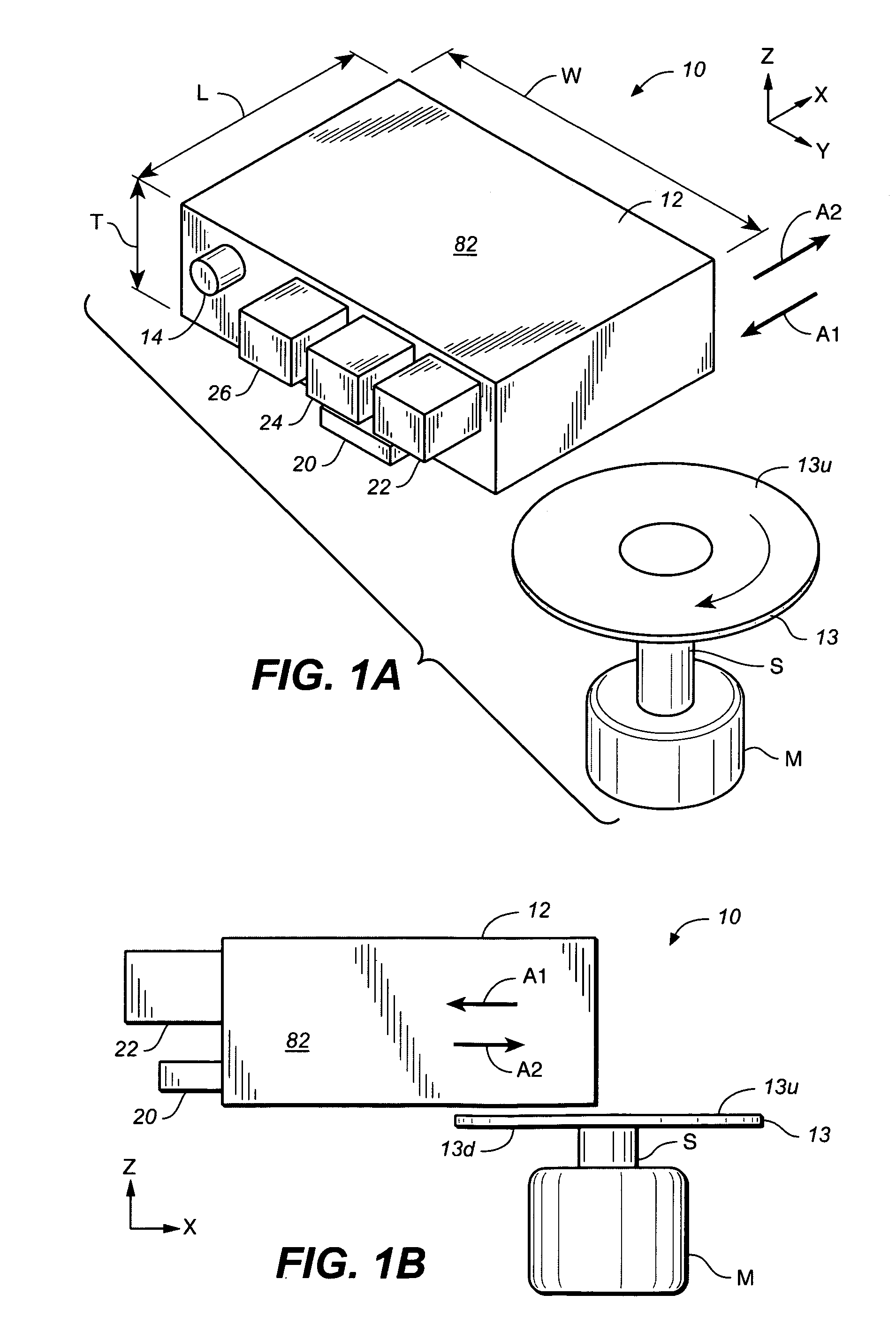
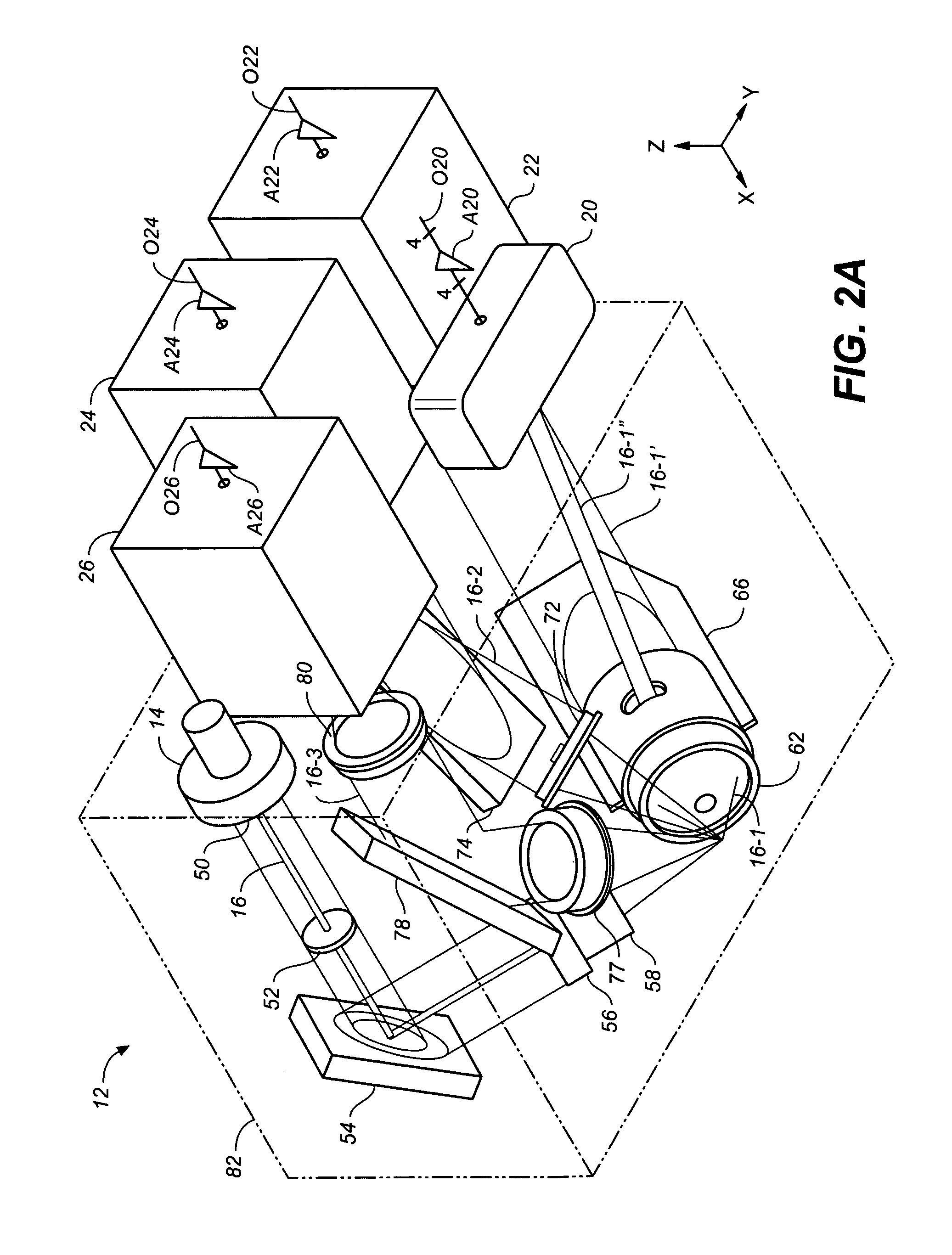
[0041]FIGS. 1A, 1B, 2A and 2B schematically illustrate an example of an optical inspection apparatus 10 in accordance with the invention that includes a head 12 for optically inspecting a top surface 13u of a workpiece 13 (typically a platter). (FIGS. 1A and 1B show the exterior of head 12 in schematic form. The actual appearance of head 12, in one embodiment, is shown in FIGS. 3A to 3D. FIGS. 2A and 2B show the optical paths and elements within head 12.) Head 12 comprises a laser source 14...


PUM


Abstract

A manufacturing cell for inspecting workpieces such as magnetic disk substrates comprises an input conveyor for providing workpieces to be tested, one or more testers for inspecting the workpieces, and three or more output receptacles for receiving tested workpieces. One or more robotic arms move the workpieces from the input conveyor to the tester and from the tester to one of the output receptacles depending upon the results of the test performed by the tester. The output receptacles include a pass receptacle, a reject receptacle, and at least an additional receptacle for workpieces that are to be re-worked or studied further. If the additional receptacle is full, workpieces that would otherwise be provided to the additional bin are placed in the reject receptacle. The reject receptacle is very large, so that it is rarely filled to capacity.

Description

CROSS-REFERENCE TO PROVISIONAL PATENT APPLICATION [0001]This application claims priority based on U.S. provisional patent application No. 60 / 643,748, filed Jan. 13, 2005.BACKGROUND OF THE INVENTION [0002]This invention relates to methods and apparatus for inspecting workpieces such as substrates used to make magnetic disks or magnetic disks during any point in the manufacturing process (including the finished disk).[0003]Magnetic disks are typically manufactured using the following method.[0004]1. A disk-shaped substrate (typically an Al alloy) is lapped or ground.[0005]2. A material such as a nickel phosphorus alloy is plated onto the substrate.[0006]3. The plated substrate is polished and textured. (During texturing, texture grooves are typically formed in the substrate by mechanical abrasion to cause a subsequently deposited magnetic layer to exhibit anisotropy. It is also known to laser texture substrates for tribological reasons.)[0007]4. One or more underlayers, one or more ma...

Claims


Application Information

Patent Timeline
Patent Type & Authority Patents(United States)
IPC IPC(8): B07C5/344
CPCG05B19/41875G01N21/9506G05B2219/32218Y02P90/02
Inventor TREVES, DAVIDO'DELL, THOMAS A.
Owner WD MEDIA
Why Eureka
Try Eureka