Hydrodynamic bearing device

a bearing device and hydrodynamic technology, applied in the direction of bearings, shafts and bearings, rotary bearings, etc., can solve the problem of difficult air removal and achieve the effect of efficient removal of air bubbles

Active Publication Date: 2007-07-10
PHC HLDG CORP
View PDF7 Cites 26 Cited by
  • Summary
  • Abstract
  • Description
  • Claims
  • Application Information

AI Technical Summary

Benefits of technology

[0008]The invention aims to provide a hydrodynamic bearing device in which the bearing performance is satisfactorily maintained in a stable state over a long period of time by circulating the operating fluid through the hydrodynamic bearing and efficiently removing the air bubbles in the operating fluid during the operation of the hydrodynamic bearing device without the operating fluid leaking outward or involving sudden fluctuation.
[0010]In the above configuration, even when one of the shaft and the sleeve is relatively rotated causing the operating fluid to circulate and flow through the inner part of the sleeve and the space between the sleeve and the cover and the air bubbles to attach to the dynamic pressure generating grooves and the like of the radial hydrodynamic bearing, the air bubbles break away from the dynamic pressure generating groove and circulate by the circulation flow, and when flowing into the fluid storage space from the communicating path through the introducing minimum clearance, the air bubbles are separated from the operating fluid and exhausted through the vent hole. Thus, lowering of bearing function such as, lowering of bearing stiffness due to air bubbles and instability of rotation during rotating operation is prevented.
[0011]One aspect of the invention is that the fluid storage space is formed into a shape that inclines with respect to the circumferential direction so that a separating distance from the end face on the open end of the sleeve becomes larger from the introducing minimum clearance toward the vent hole side. According to such configuration, even when the hydrodynamic bearing device is subjected to an external impact or the orientation is suddenly changed, the interface between the air and the operating fluid in the fluid storage space remains in the proximity of the vent hole and is prevented from moving in the circumferential direction. Thus, leaking of the operating fluid to the outside involved in the movement of the air bubbles can be prevented. Further, at the location in the proximity of the vent hole, the interface has a shape that changes in the circumferential direction, and thus fluctuation of the area of the interface or the surface tension involved therewith is small.
[0013]A still further aspect of the invention is that an operating fluid storing part for storing the operating fluid in communication with the outside air is formed on the inner peripheral surface facing the shaft of the cover, the operating fluid storing part including an inclined surface that inclines so that an inner diameter of the cover becomes larger as the distance from the end face on the open end of the sleeve becomes larger, and the inner diameter of the operating fluid storing part is formed into a shape in which a surface tension of the operating fluid stored in the operating fluid storing part and a surface tension of the operating fluid facing the vent hole are substantially balanced. According to such configuration, a sudden change in the position of the interface and the leakage of the operating fluid caused by such change in interface can be prevented.
[0014]Another aspect of the invention is that an operating fluid storing part for storing the operating fluid in communication with the outside air is formed on the outer peripheral surface of the shaft facing the inner peripheral surface of the cover, the operating fluid storing part including an inclined surface that inclines so that an outer diameter of the shaft becomes smaller as the distance from the end face on the open end side of the sleeve becomes larger, and the operating fluid storing part is formed into a shape in which a surface tension of the operating fluid stored in the operating fluid storing part and a surface tension of the operating fluid facing the vent hole are substantially balanced. According to such configuration, in addition to the sealing effect by the surface tension in a stationary state, a sealing effect by a centrifugal force generated through shaft rotation during the operation is also provided, thereby preventing a sudden change in the position of the interface and the leakage of the operating fluid caused by such change in interface.
[0019]According to the hydrodynamic bearing device of the invention, during the rotating operation of the shaft, the operating fluid in the dynamic pressure generating groove of the radial hydrodynamic bearing flows toward the dynamic pressure generating groove of the thrust hydrodynamic bearing, passes through the communicating path, through a narrow clearance formed between the end face on the open end of the sleeve and the cover by the capillary phenomenon, and flows back to the dynamic pressure generating groove of the radial hydrodynamic bearing. When the operating fluid flows back, the air contained as air bubbles is separated from the fluid in a fluid storage space that is also formed between the end face on the open end side of the sleeve and the cover and that is greater than the clearance, and only the air is released outside from the vent hole. Thus, the air in the operating fluid is gradually removed. Since the operating fluid does not leak out from the vent hole, the HDD device can be prevented from being polluted. Particularly, since the fluid storage space is formed into a shape that inclines with respect to the circumferential direction so that the separating distance from the end face on the open end of the sleeve becomes larger from the introducing minimum clearance toward the vent hole, even when the hydrodynamic bearing device is subjected to an external impact or the orientation thereof is suddenly changed, the leakage of the operating fluid to the outside involved in the movement of the air bubbles can be prevented. Therefore, lowering of bearing function such as, lowering of bearing stiffness due to air bubbles and instability of the rotation during rotating operation can be prevented, and further, the operating fluid can be reliably prevented from leaking outward and thus reliability can be enhanced.

Problems solved by technology

Further, rotation of the hydrodynamic bearing device may involve and mix small air bubbles in the operating fluid.
In this conventional type of hydrodynamic bearing device, the fluid from where air (air bubble) is removed in advance is used in filling of the fluid in the assembly step, but complete removal of air is difficult.

Method used


Image

  • Hydrodynamic bearing device
  • Hydrodynamic bearing device
  • Hydrodynamic bearing device

Examples


first embodiment

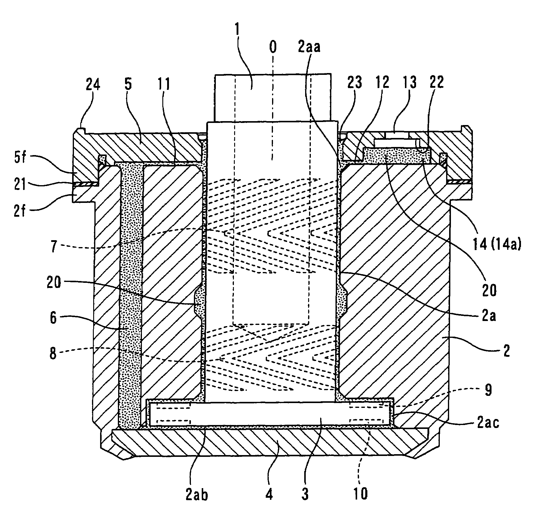
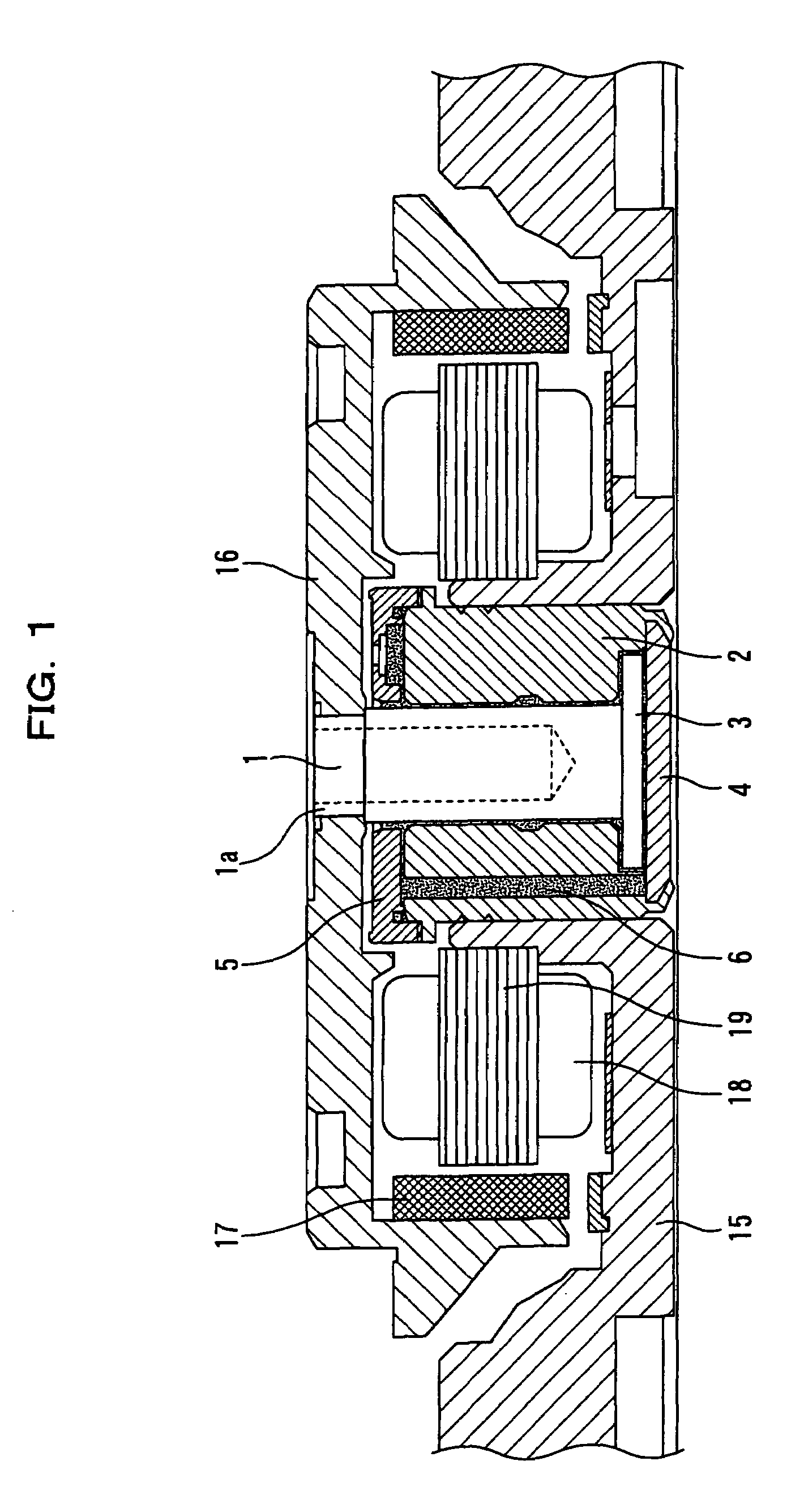
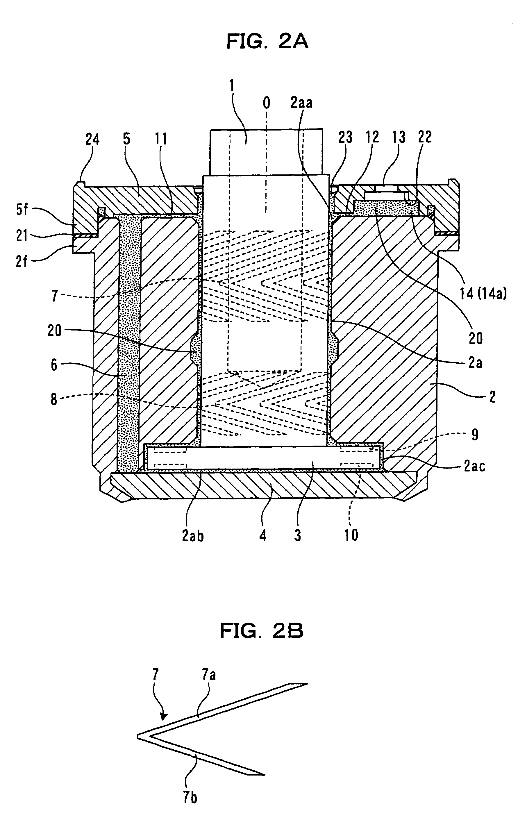
[0045]FIG. 1 is a cross sectional view of a spindle motor equipped with a hydrodynamic bearing device according to a first embodiment of the invention, FIG. 2A is a cross sectional view of the hydrodynamic bearing device, FIG. 3 is a plan view of the hydrodynamic bearing device, and FIG. 2A is a cross sectional view taken along line II-II of FIG. 3. In the following description, a case in which an open end of a bearing hole of the sleeve is arranged upward and a close end is arranged downward, as shown in FIG. 1 and FIG. 2A, is explained for easy understanding, but in actual use, the arrangement is of course not limited thereto.

[0046]In FIG. 1 and FIG. 2A, the components made of the following materials are used.

[0047]A shaft 1 made of stainless steel is used, and a flange 3 made of stainless steel having hardness lower than that used for the shaft 1 is used since the flange 3 is integrally fixed to the shaft 1 and is formed with a dynamic pressure generating groove. A sleeve 2 is ma...

second embodiment

[0077]A hydrodynamic bearing device of a configuration different from the hydrodynamic bearing device of the first embodiment described above will now be described. In the following description, a case in which the open end of the bearing hole of the sleeve is arranged upward and the close end is arranged downward, as shown in FIG. 15B, is explained for easy understanding, but the orientation of arrangement is not limited thereto.

[0078]As shown in FIGS. 15A and 15B, the hydrodynamic bearing device includes, in addition to a configuration including a shaft 71, a sleeve 72 including a bearing hole 72a with an open end on the upper side that opens and a close end on the lower side that is closed and having the shaft 71 inserted therein in a freely rotating orientation with a gap (space) in between, a thrust flange 73 of thick diameter arranged on the one end part (lower end part in FIG. 15B) of the shaft 71 and arranged in an orientation that includes a gap with respect to the end face...


PUM


Abstract

A hydrodynamic bearing device in which an introducing minimum clearance for causing capillary phenomenon is formed from the location in the proximity of the opening of a communicating path to the open end of the bearing hole in between the cover and the end face on the open end of the sleeve so that the operating fluid from the communicating path in the sleeve flows into the bearing hole by the capillary phenomenon; a vent hole leading to the outside air is formed on the cover; a fluid storage space for storing the operating fluid is formed on the inside surface of the cover or the end face on the open end of the sleeve to communicate the introducing minimum clearance and the vent hole in the circumferential direction; and the air bubbles separated at the fluid storage space are exhausted outward from the vent hole.

Description

FIELD OF THE INVENTION[0001]The invention relates to a hydrodynamic bearing device used in a spindle motor and the like for rotatably driving a magnetic disc, an optical disc and the like.DESCRIPTION OF THE RELATED ART[0002]Instead of a ball bearing device conventionally used, a hydrodynamic bearing device excelling in rotating precision and silence than the ball bearing is widely adopted for the bearing device used in the spindle motor and the like of a hard disk drive.[0003]This type of hydrodynamic bearing device includes a hydrodynamic bearing device disclosed in, for example, JP-A 11-82486 (1999). As shown in FIG. 18, the hydrodynamic bearing device includes a shaft 51, a sleeve 52 arranged on the outer periphery of the shaft 51 with a gap in between, and thrust flanges 53 and 54 of thick diameter arranged on both ends of the shaft 51 and arranged in an orientation that includes a gap with respect to both end faces of the sleeve 52. An operating fluid consisting of lubricant oi...

Claims


Application Information

Patent Timeline
Patent Type & Authority Patents(United States)
IPC IPC(8): F16C32/06
CPCF16C17/107F16C33/103F16C33/107F16C33/726F16C33/745F16C2370/12F16C2240/40
Inventor UENOSONO, KAORUYOSHIKAWA, YOSEISAKATA, AKIRAASADA, TAKAFUMI
Owner PHC HLDG CORP
Why Eureka
Try Eureka