Device for the insulation of stator slots

a stator slot and slot insulation technology, applied in the direction of windings, mechanical energy handling, dynamo-electric components, etc., can solve the problems of insufficient insulation of stators against phase windings, leakage current paths, and high labor intensity of processes, and achieve low tool manufacturing costs, less material thickness, and favorable wall thickness geometry

Active Publication Date: 2007-07-10
MINEBEAMITSUMI INC
View PDF14 Cites 12 Cited by
  • Summary
  • Abstract
  • Description
  • Claims
  • Application Information

AI Technical Summary

Benefits of technology

[0009]The covering piece can be designed, for example, as an annular cover plate that is held on the insulating body with a spacing to the moldings in order to enclose the winding head between the insulating body and the cover plate. Such cover plates could also be provided at both end faces of the stator. This embodiment has the advantage that the device for the insulation of the stator slots can simultaneously take on the function of covering the winding head so that the windings are carried (guided) on the outside of the stator, they are protected from outside influences and other motor parts can be fastened to the stator.
[0012]The invention further provides a two-piece insulating body that has a first part and a second part having moldings adapted to the shape of the stator slots of the stator. The two parts of the insulating body can be slid onto the stator on both sides in an axial direction, each part of the insulating body being dimensioned in the axial direction so that after they have been slid onto the stator, the moldings adapted to the stator slots extend at least partially over the axial length of the stator slots and overlap one another in the axial direction. In the region in which the two parts of the insulating body overlap, a first group of moldings of the first part engage into the moldings of the second part located opposite, and a second group of moldings of the first part encompass moldings of the second part located opposite. In contrast to the prior art, the two parts of the insulating body do not adjoin each other with planar faces. They are also not designed for the first part to be inserted fully into a second part in an overlapping region, or vice versa. In fact, the two parts of the insulating body are so designed that in the region of overlap, one part of the moldings of the first part encompasses the corresponding moldings of the second part and another part of the molding of the first part is inserted into the corresponding moldings of the second part. For a stator having an even number of poles or slots, the moldings of the first and of the second part are preferably designed so that they are alternatively inserted into or encompass the corresponding opposing moldings of the respective other parts. This goes to create a particularly intimate contact between the two parts of the insulating body, and air pockets as well as air gaps in the region of overlap can be extensively eliminated. In a beneficial embodiment of the invention, the two parts of the insulating body are identical in construction and are slid one on top of the other in the region of overlap. This has the advantage that identical insulating bodies can be manufactured at low tool manufacturing costs.
[0014]The different embodiments of the insulating body mentioned above have the advantage that after the two parts of the insulating body have been joined together, an even, continuous insulating layer is created that fits snugly against the slots and poles of the stator and insulates them in a reliable way without the risk of air pockets or gaps being formed.

Problems solved by technology

A gap between the two parts of the insulating body can result in the hammers of the stator not being sufficiently insulated against the phase windings.
Moreover, an air gap between the insulation and the stator material carries the risk that leakage current paths may be formed.
This process is very labor intensive, the phase windings of the wound stator very often being arranged in a confused manner and it being difficult to identify exactly where the respective winding ends are led out of the stator.

Method used


Image

  • Device for the insulation of stator slots
  • Device for the insulation of stator slots
  • Device for the insulation of stator slots

Examples


Embodiment Construction

[0022]The invention is described below using a brushless DC motor having an inner rotor configuration as an example. The person skilled in the art, however, would realize that the principles of the invention can be applied to any type of electric motor or generator.

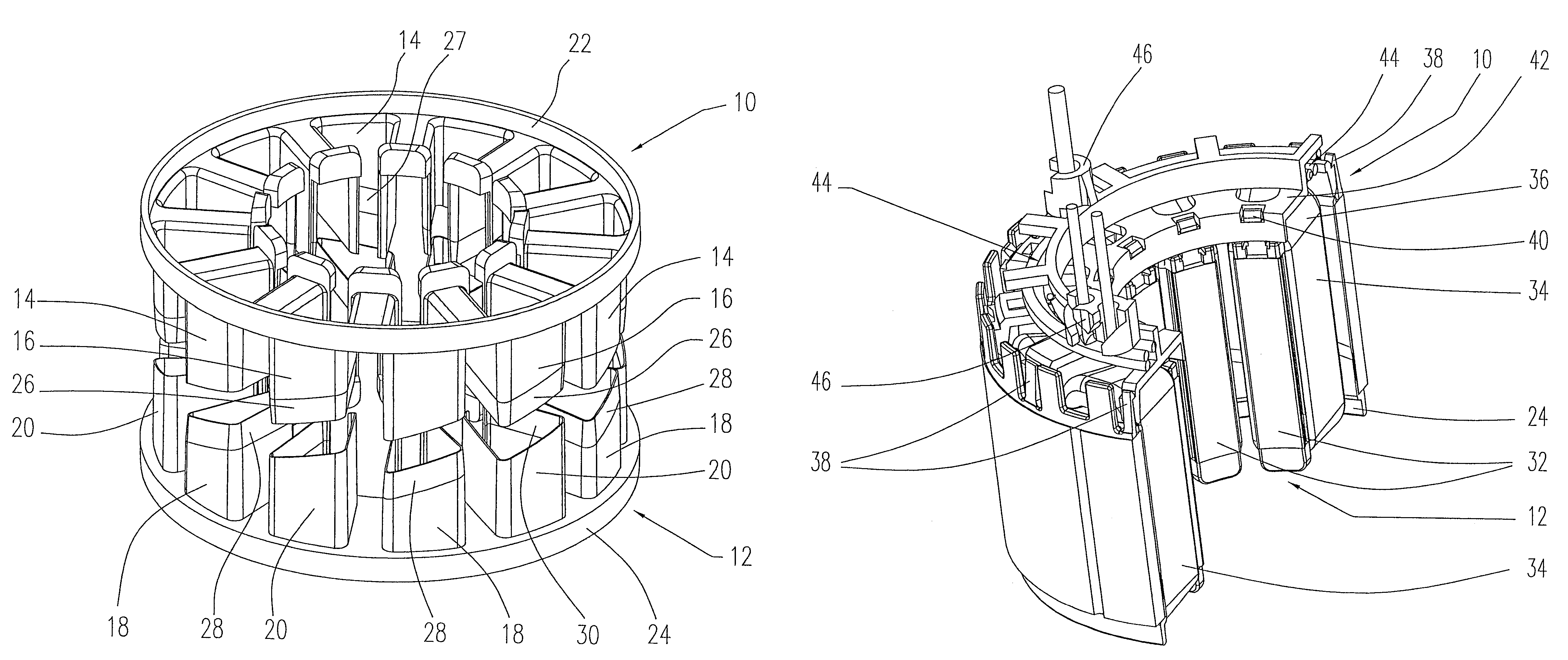
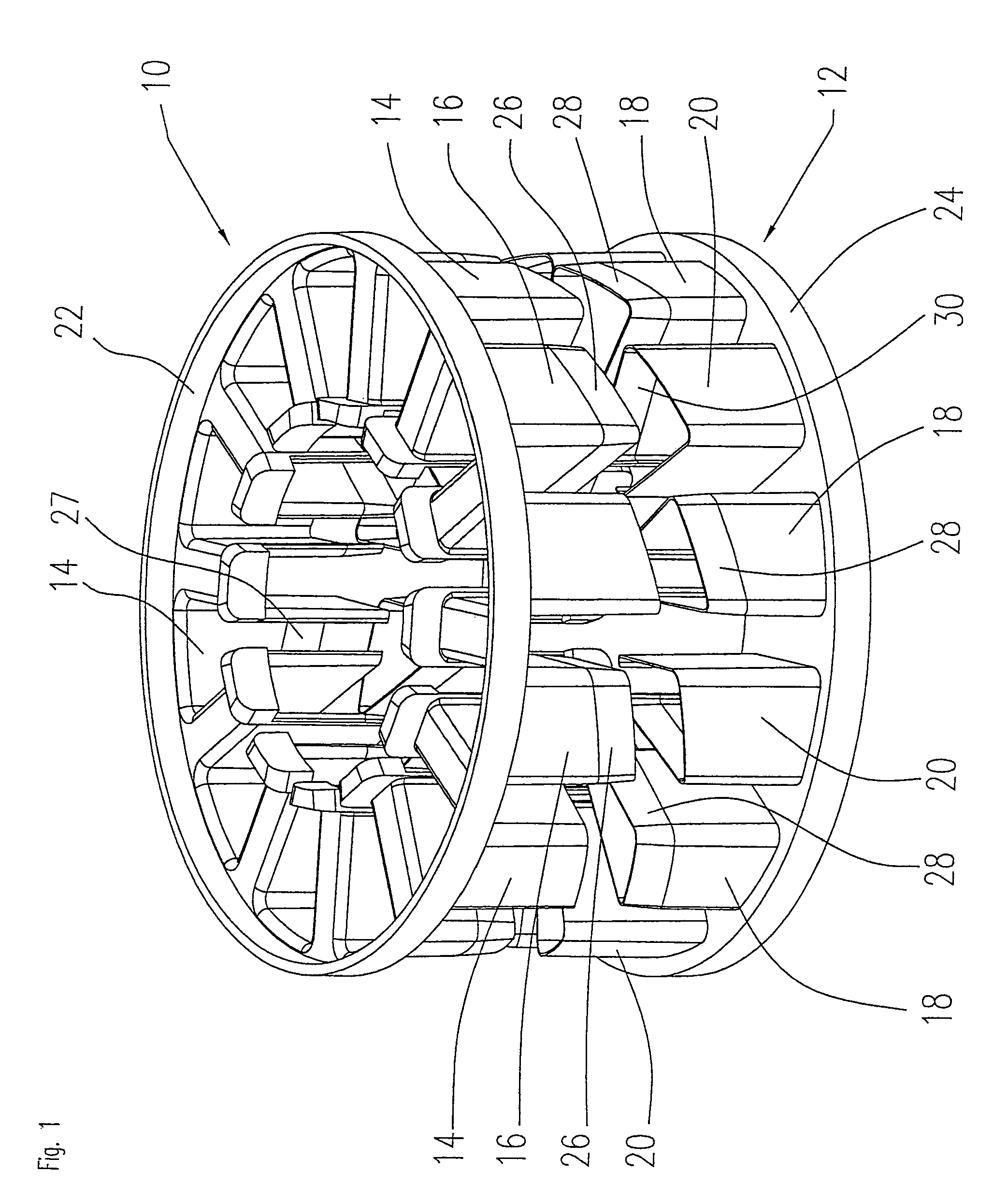
[0023]FIG. 1 shows a perspective view of a two-piece insulating body according to the invention. The insulating body comprises a first part 10 and a second part 12. Each of the two parts 10, 12 of the insulating body is provided with moldings 14, 16, 18, 20 which are adapted to the shape of the stator slots of a stator on which the insulating body 10, 12 is to be mounted. It can be seen from FIG. 1 that each of the moldings 14, 16, 18, 20 lines a stator slot completely, the side faces of the pole, or hammer, located between two stator slots being provided with an insulating sleeve through adjoining moldings. In the illustrated embodiment, the moldings 14, 16 of the first part 10 and the moldings 18, 20 of the second part ...


PUM


Abstract

The invention relates to a device for the insulation of the stator slots of an electric machine that has a stator having a plurality of stator poles and stator slots located between the stator poles, comprising an insulating body that has moldings adapted to the shape of the stator slots and can be slid onto the stator in an axial direction, and a cover piece that can be connected to an end face of the insulating body, in order after the windings have been applied to the insulating body, to carry the windings (36) at the end face of the stator and to cover them.

Description

[0001]The instant disclosure claims the filing-date benefit of German Utility Model Application No. 20 2004 010 956.5 filed Jul.13, 2004, the specification of which is incorporated herein in its entirety.FIELD OF THE INVENTION[0002]The invention relates to a device for the insulation of the stator slots of an electric machine that has a stator having a plurality of stator poles and stator slots located between the stator polesBACKGROUND OF THE INVENTION [0003]A main area of application of the invention is in the field of brushless DC motors and other permanent magnet motors which are configured as inner rotor motors or as outer rotor motors. The invention, however, is not limited to this area and can be generally applied to any kind of electric motor or generator.[0004]Electric motors having an inner rotor configuration have a rotor arrangement that is mounted onto the shaft and comprises one or more permanent magnets, as well as a stator arrangement made up, for example, of a numbe...

Claims


Application Information

Patent Timeline
Patent Type & Authority Patents(United States)
IPC IPC(8): H02K3/34H02K5/00H02K7/00H02K3/38H02K3/50H02K3/52
CPCH02K3/345H02K3/38H02K3/522H02K3/50
Inventor SCHNEIDER, HELMUTKREIENSEN, ULRICH
Owner MINEBEAMITSUMI INC
Why Eureka
Try Eureka