Optical fiber clad-protective terminations

a technology of protective terminations and optical fibers, applied in the direction of optics, optical waveguide light guides, instruments, etc., can solve the problems of fibers not being able to transmit well, laser misalignment or beam shift risk, damage or complete destruction, etc., to achieve convenient connection to hardware, fiber termination structure is cheaper, and the effect of being durabl

Active Publication Date: 2007-07-10
NAVY U S A AS REPRESENTED BY THE SEC OF THE THE
View PDF17 Cites 63 Cited by
  • Summary
  • Abstract
  • Description
  • Claims
  • Application Information

AI Technical Summary

Benefits of technology

[0006]It is an object of this invention to provide a termination structure which blocks an input laser beam from impinging on the microstructured region and imparting damage thereto.
[0008]Another object of this invention is to make a fiber termination structure multifunctional in that it can be used to protect hollow core and solid core fiber, and the like.
[0009]Another object of this invention is to make a fiber termination structure cheaper, more durable and readily connectable to hardware, such as other optical fibers and optical systems.

Problems solved by technology

Although over 99% of the light is predicted to propagate in the fiber core, where a laser beam can be focused into, there is always a risk of laser misalignment or beam shift due to temperature or environmental changes.
If the beam impinges on the microstructured region, damage or complete destruction usually occurs whereby the fiber is ablated or otherwise damaged and cannot be used for optical transmission.
However, it turns out that hollow core photonic bandgap silica fibers do not transmit well beyond 2 μm since up to several percent of the light can propagate in the microstructured region and this light is highly attenuated through multiphonon absorption in silica.
Hence, it is not possible to use silica photonic bandgap fibers for high power transmission in the infrared region beyond a wavelength of about 2 μm.

Method used


Image

  • Optical fiber clad-protective terminations
  • Optical fiber clad-protective terminations
  • Optical fiber clad-protective terminations

Examples


Embodiment Construction

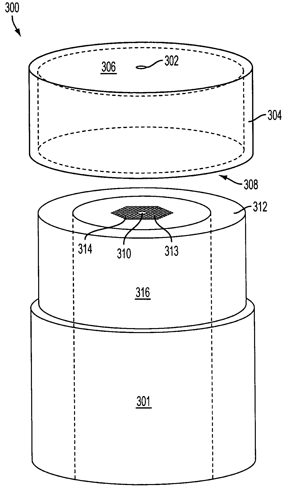
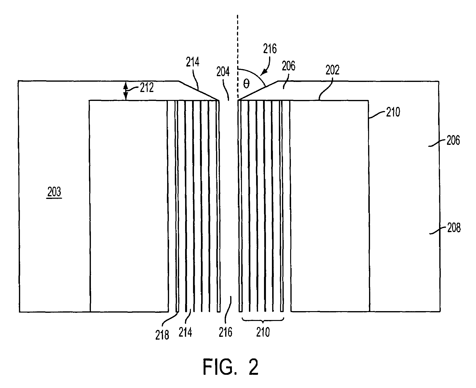
[0014]This invention pertains to an optical fiber termination structure to eliminate and / or reduce damage to an optical fiber, including a region of the fiber containing multiple longitudinal channels separated from each other by thin walls, as thin as on the order of 150 nanometers, the channels surrounding a fiber core. The core can be hollow or solid and the purpose of the channels is to confine the optical signal to the core region.

[0015]The optical fiber material can be any material that the fiber can be made of including, but not limited to, glass, plastic and metal or alloy. In a preferred embodiment, the material is a chalcogenide glass. The core of the fiber can be solid but is typically hollow, filled with air or some gas, at higher than atmospheric or at atmospheric pressure, or it can be a vacuum. Laser induced damage threshold for air at 1 μm wavelength in a hollow core has been reported to have maximum measured intensity of about 1014 watts / cm2 at a low (e.g. 10 Torr) ...


PUM


Abstract

This invention pertains to fiber termination combination which includes an optical fiber having a fiber core for transmitting a highly energetic optical signal that can damage the fiber and a structured region around the core for directing the optical signal into the core, the structured region being characterized by multiple channels of smaller internal diameter than the core defined by thin walls disposed around said core; a ferrule, with an opening therein for locating said fiber, at the end of said fiber enveloping said fiber extremity which cooperates with said blocking structure to block the optical signal from impinging on said microstructured region of said fiber; and a blocking structure disposed over the end of said fiber with an opening mating with said fiber core, said blocking structure blocking the optical signal from impinging on said microstructured region of said fiber.

Description

BACKGROUND OF THE INVENTION[0001]1. Field of the Invention[0002]This invention pertains to the optical fiber terminations whereby damage to the fiber, and particularly to the microstructured region thereof containing channels separated by thin walls, is eliminated and / or reduced.[0003]2. Description of Related Art[0004]In developing the hollow core photonic band gap fibers for various applications, the most important of which is for transmission of ultra-high laser power in the infrared, on the order of tens of giga watts per square centimeter, the fibers are intended for implementation in missile warning protection systems for military and commercial aircraft. The fibers can also be used in laser surgery with optical beams at various wavelengths, including wavelengths of 2.94 μm and 10.6 μm. These fibers typically consist of a hollow, air-filled core and a microstructured cladding surrounded by a solid glass jacket for mechanical strength as shown in FIG. 1. The microstructured cla...

Claims


Application Information

Patent Timeline
Patent Type & Authority Patents(United States)
IPC IPC(8): G02B6/38G02B6/00G02B6/02G02B6/32
CPCG02B6/262G02B6/02347G02B6/4296
Inventor BUSSE, LYNDAKUNG, FREDERIC H.SANGHERA, JASBINDERAGGARWAL, ISHWAR
Owner NAVY U S A AS REPRESENTED BY THE SEC OF THE THE
Why Eureka
Try Eureka