
Air blanketed food preparation table

a technology of food preparation table and air blanket, which is applied in the direction of lighting and heating apparatus, show cabinets, domestic cooling devices, etc., and can solve problems such as adversely affecting performan

Inactive Publication Date: 2007-07-17
QUALSERV HLDG
View PDF17 Cites 14 Cited by
  • Summary
  • Abstract
  • Description
  • Claims
  • Application Information

AI Technical Summary

Benefits of technology

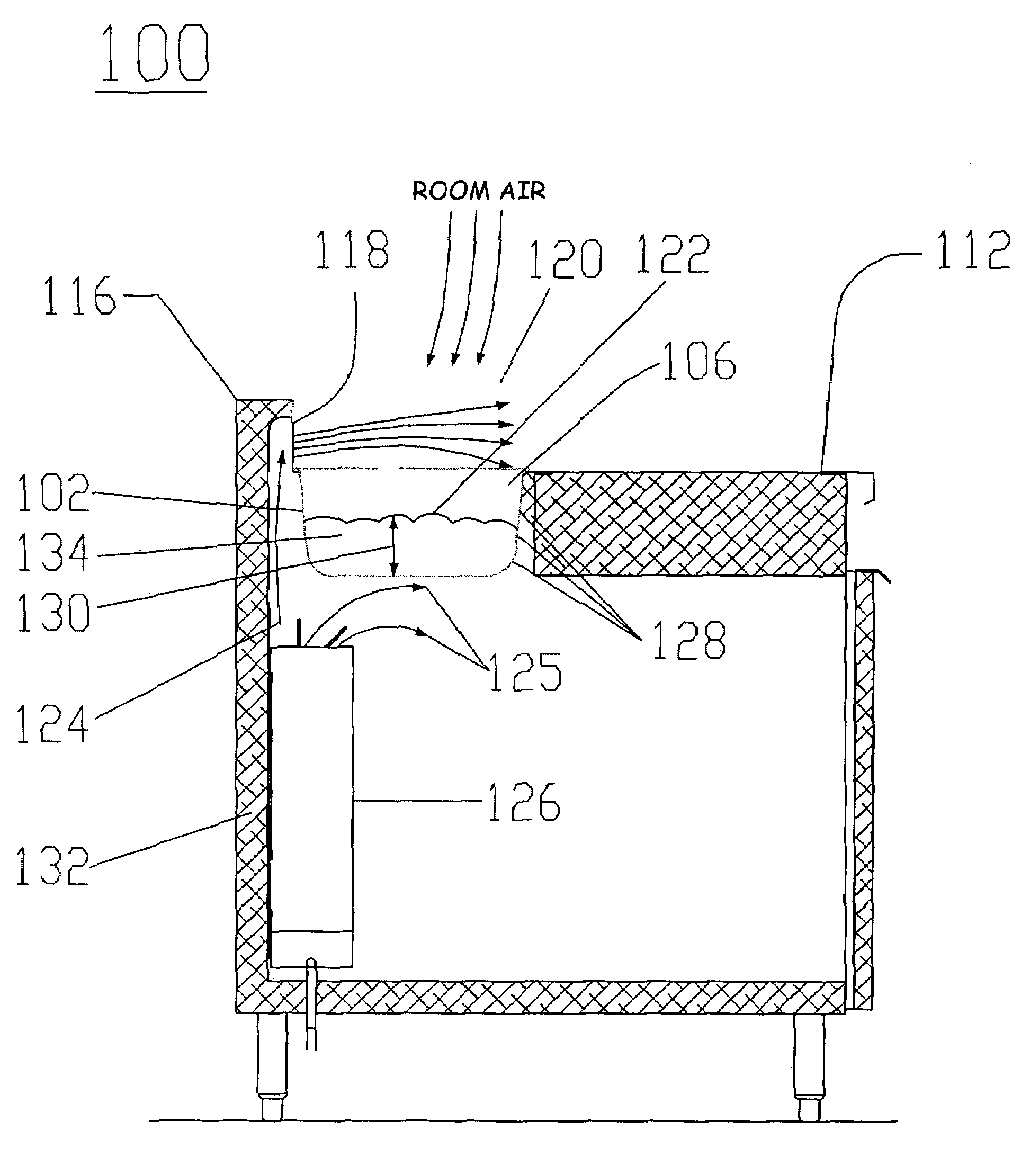
[0019]Experimentation has shown that low velocity chilled air may provide an insulating boundary layer of cooler air (40° F. to 55° F.) immediately above the held food product surfaces. This boundary layer retards the negative impact of infiltrating warm air on the bulk food temperature so such a boundary layer will readily satisfy the NSF 7 target of 41° F. or less for the required 4 hour period after food is placed in the open well. Food shelf life is extended without the risk of localized freezing or drying of the top surface of the held food product. Embodiments of the invention work equally well with either plastic or metal food containers or pans.
[0020]Because standard commercial components are used with minimal modification (for example, the addition of adjustable air baffles and air vents to pre-existing make-table designs), manufacturing costs are not adversely impacted and the open well “air blanketed” or “air quilt” work stations of the invention may be competitively priced. Experimentation has shown that better results can be obtained when a make-table made in accordance with the principles of the invention is operated with all pans in place and subjected to little or no local air currents (such as fans or ventilation supply flow) directed at the food pans. Otherwise, the insulating layer may be disrupted which may adversely impact performance. Standard regulation of the base storage temperature using a chilled-air source, such as, for example, a top discharge fan coil evaporator with one change-continuous operation of the fan, which runs even if freon or other refrigerant is not flowing as the interior desired temperature is satisfied, allows make-tables of the invention to meet the expected performance standards. Typically the wells should be emptied and night covers used when the work station is not staffed to maximize the system thermodynamic efficiency and reduce energy usage.
[0026]The food pans typically include multiple pans or rows of food pans, which may be disposed to receive chilled air from the air duct. At least one row of the multiple rows of food pans may be positioned at a different level than another row of food pans, and the air duct may include a first and a second spaced air duct, with each duct conducting low velocity chilled air into at least one row of the multiple rows of food pans. The second air duct may direct chilled air at low velocity in a direction substantially opposite to the direction air emanates from the first air duct, or the first and second air ducts may have vents facing in substantially similar directions. Finally, a raised barrier maybe disposed in a position substantially surrounding the at least one food pan to help isolate low velocity chilled air directed thereto from ambient air.
[0027]In another aspect of the invention, a method of maintaining or decreasing the temperature of food in a food pan of a refrigerated make-table is provided, including: i) placing the food pan at least partially within a food pan well in the make-table; ii) directing chilled air to the food pan; and iii) controlling the velocity of the chilled air to permit the chilled air to create a protective boundary layer of chilled air disposed above the food in the food pan, thereby providing an air blanket insulating the food pan from ambient air and maintaining an interior temperature of the food pan at a temperature of about 35° F. to about 41° F. The velocity controlling step may include directing chilled air over the food pan at a velocity of less than about 100 feet per minute, and preferably, in a range of approximately 8 feet per minute to approximately 75 feet per minute.

Problems solved by technology

Otherwise, the insulating layer may be disrupted which may adversely impact performance.

Method used


Image

  • Air blanketed food preparation table
  • Air blanketed food preparation table
  • Air blanketed food preparation table

Examples


third embodiment

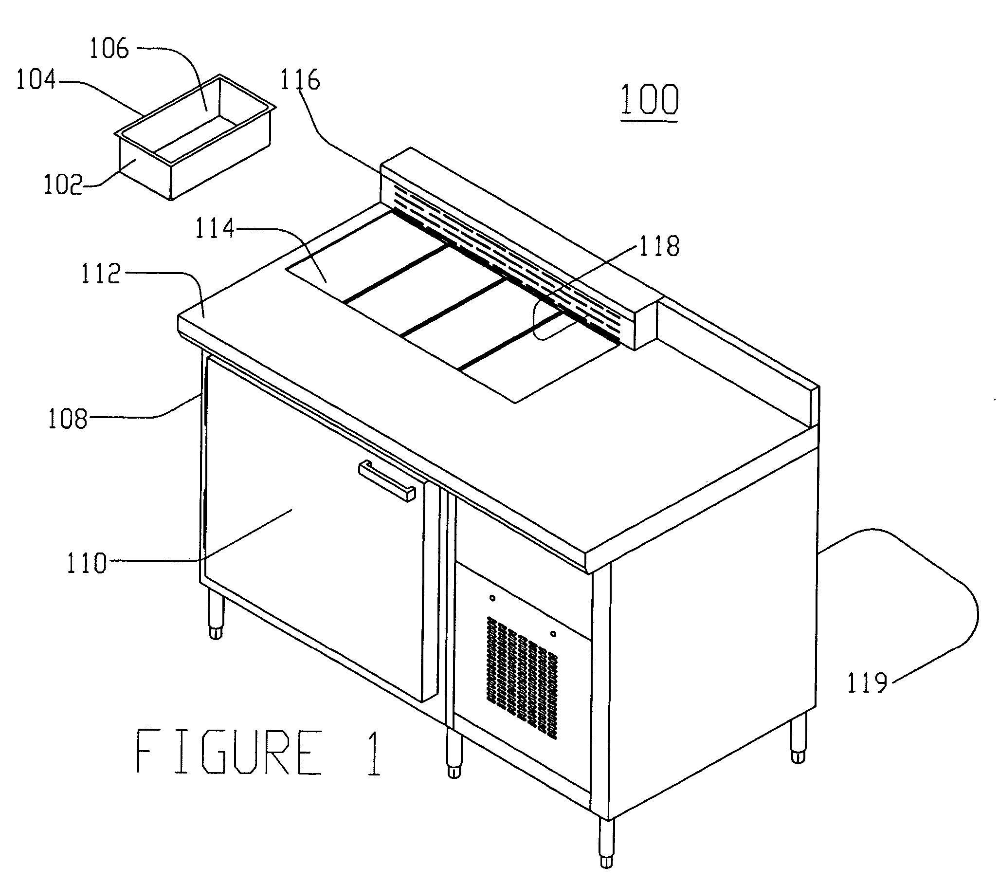
[0083]Referring to FIG. 8, a food preparation table 300 of the invention having a single row of food pans arranged in a single step configuration is shown. Features or components similar to the previously described embodiments may not be discussed in detail herein. The food preparation table 300 has a cabinet 308, which has a front surface 310 and a top surface 312. The cabinet 308 includes a cooling housing 320 for housing a compressor or similar unit for cooling the table. Disposed within the top surface 312 of the food preparation table 300 are 14 food pan wells 302 provided in two groups of seven pans. The 14 food pan wells 302 are configured to hold food pans therein and are arranged in a row near the back of the top surface 312. Next to the food pan wells 302 is air header assembly 316 provided in a raised rail. The air header assembly 316 has a series of air vents 318 therein. The air vents 318 are positioned to direct chilled air from the interior of the table over and into ...

fourth embodiment

[0086]Referring to FIGS. 11 and 12, a food preparation table 400 of the invention having two rows of food pans arranged in a single step configuration is shown. Again, features or components similar to prior embodiments may not be described in detail. Referring to FIG. 11, the food preparation table 400 includes a cabinet 408 having a housing 420 for a compressor or similar unit. The food preparation table 400 has a top surface 412 with a series of openings 401 and 405 for a first row of food pans 402 and a second row of food pans 403. Adjacent to the first row of food pans 402 is air header assembly 416 providing a raised rail with air vents 418 therein. The food preparation table 400 has a front surface 410 which may have doors therein for access into an interior of the food preparation table 400.

[0087]As shown in FIG. 12, a cross section of the food preparation table 400 shows a first row of food pans 402 next to air vents 418 of air header assembly 416, and a second row of food ...

fifth embodiment

[0090]FIGS. 13 and 14 show a food preparation table 500 constructed according to the principles of the invention having three rows of food pans arranged in a single step configuration. As shown in FIG. 13, the food preparation table 500 has a cabinet 508 with a cooling unit housing 520. The cabinet 508 has a front 510 and a top surface 512. At a rear portion of the top surface 512 is a raised rail having an air header assembly 516 with air vents 518 therein. Disposed in the top surface 512 of the food preparation table 500 is a first row 502, a second row 503, and a third row 505 of food pans. The first row of food pans 502 is arranged next to the air header assembly 516 and vents 518. The second row of food pans 503 is between the first row of food pans 502 and the third row of food pans 505. Accordingly, the first row, second row, and third row of food pans 502, 503 and 505 are arranged so that each row may sequentially receive low velocity chilled air discharged from the air vent...


PUM


Abstract

A method and apparatus is provided to cool and / or protect chilled food in a food pan from warmer ambient air by passing low velocity chilled air from air vents proximate the food pan into and / or over the food pan to form a relatively stable mass of cooled air within the interior of the food pan. The low velocity air may also form a slowly moving barrier of chilled air that hinders warmer ambient air from reaching the food pan. Various embodiments employing numerous arrangements of food pans, cooling system and air ducts configured to direct the chilled air at a low velocity into and / or over the food pans are disclosed.

Description

BACKGROUND OF THE INVENTION[0001]1. Field of the Invention[0002]The invention relates generally to cold food preparation tables having open food pans or wells commonly used for pizza, sandwiches, and salad preparation tables (also know as make-tables), and more particularly to an improved make-table that readily complies with model food code standards requiring refrigerated food items to be stored at temperatures of 41° F. or less.[0003]2. Background and Related Art[0004]The restaurant industry utilizes various types of specialized equipment to store food in a cold environment while streamlining food preparation. In particular, food items must be either cold or hot while being stored just prior to serving. Such temperature requirements are based on maintaining the food at a temperature that inhibits bacterial growth as well as preserving the palatability of the food for a certain time period. Many of the safe food storage temperature requirements are based on standards adopted by th...

Claims


Application Information

Patent Timeline
Patent Type & Authority Patents(United States)
IPC IPC(8): A47F3/04
CPCA47F3/0447
Inventor SPILLNER, WAYNE K.
Owner QUALSERV HLDG
Learn More