
Pivoting rear blade guard

a rear blade guard and blade guard technology, applied in the field of power tools, can solve the problems of user dissatisfaction, interference with the saw's vertical cutting ability, and limited saw vertical cutting ability, and achieve the effect of greater cutting capacity

Active Publication Date: 2007-07-17
BLACK & DECKER INC
View PDF27 Cites 27 Cited by
  • Summary
  • Abstract
  • Description
  • Claims
  • Application Information

AI Technical Summary

Benefits of technology

The present invention is about a saw blade guard that can pivot to increase cutting capacity. The guard can be positioned in different orientations, and it can be pushed to a guarding position by a biasing device. This allows for more efficient cutting and reduces the risk of injury from using the saw.

Problems solved by technology

A drawback to the previous system is that an upper or fixed guard may interfere with the saw's vertical cutting ability.
The saw's vertical cutting ability may be limited in order to cover the blade adjacent the top portion of the fence.
This limited capacity may lead to user dissatisfaction and may even require the user to reposition the workpiece in order to finish the cut.
Moreover, some guard systems may become clogged with debris during use or fail to properly direct the dust into a containment system, such as a vacuum duct.
While an extension may cover the blade, the saw's vertical capacity may be unduly limited if the extension contact the upper surface of the workpiece.

Method used


Image

  • Pivoting rear blade guard
  • Pivoting rear blade guard
  • Pivoting rear blade guard

Examples


Embodiment Construction

[0014]Reference will now be made in detail to the presently preferred embodiments of the invention, examples of which are illustrated in the accompanying drawings.

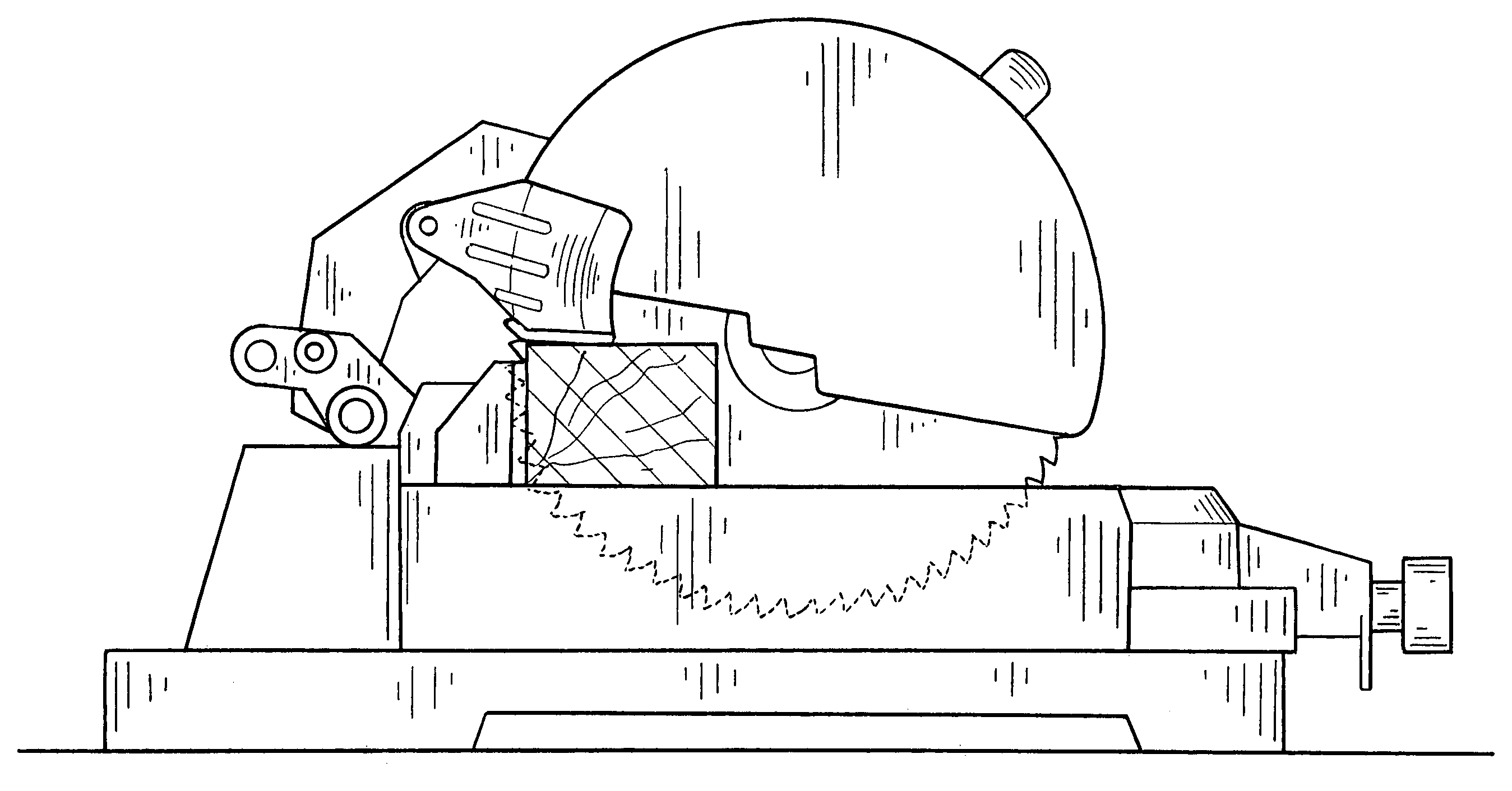
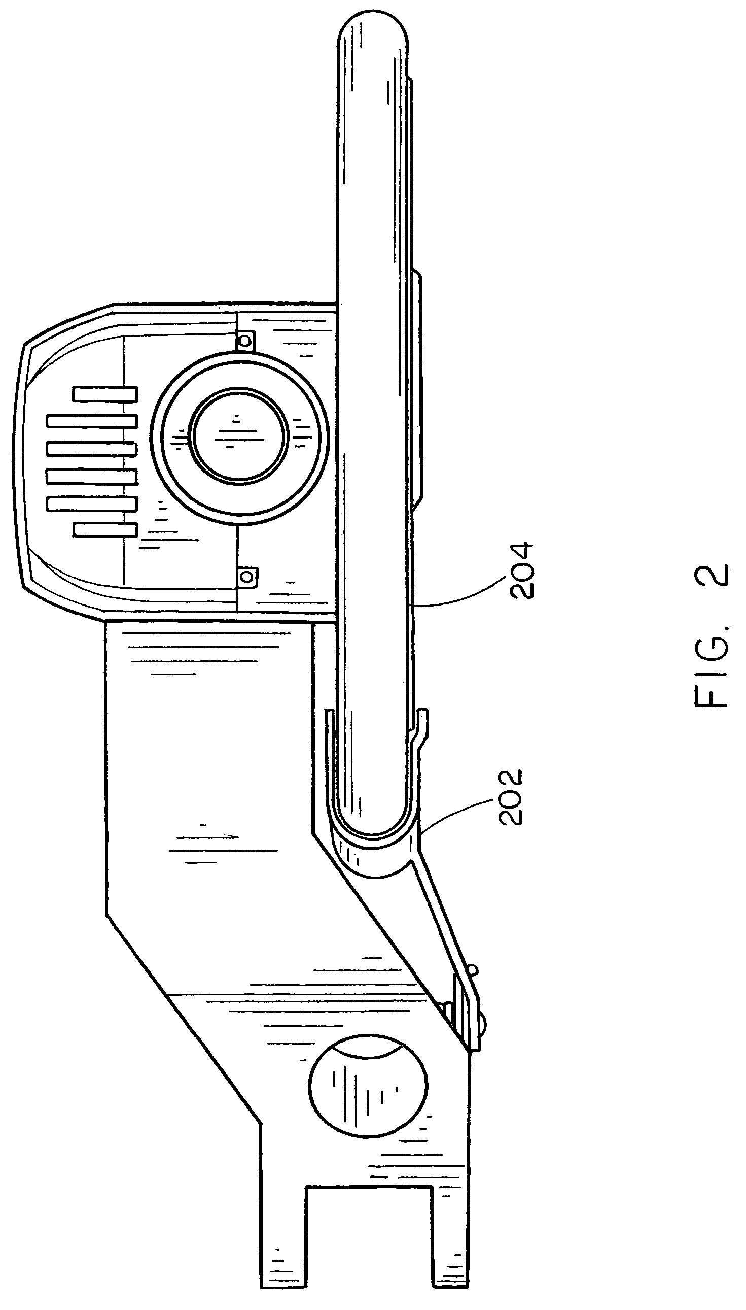
[0015]Referring generally now to FIGS. 1 through 5, exemplary embodiments of the present invention are shown. The apparatus of the present invention provides a guard capable of pivoting to generally match the workpiece while allowing for increased cutting capacity.

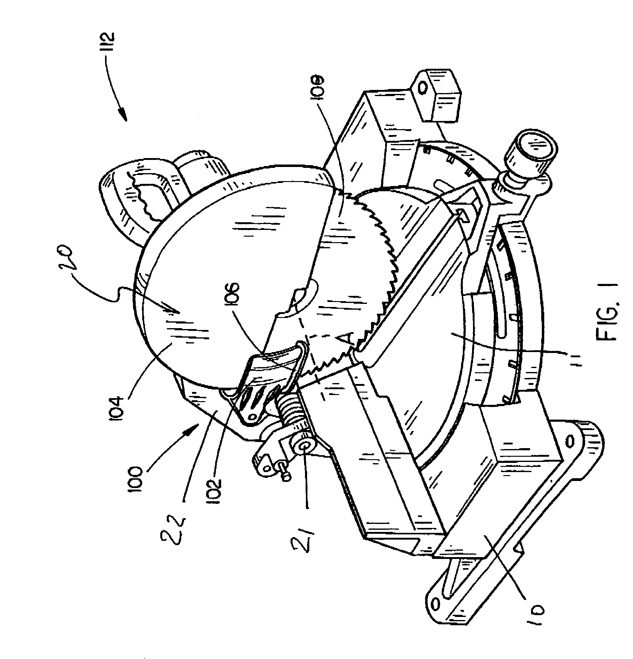
[0016]Referring to FIG. 1, a blade guard assembly 100 is described. The blade guard assembly of the present embodiment may be pivotally mounted so as to at least partially cover a saw blade while allowing for increased cutting capacity. In the current embodiment, the assembly 100 is implemented with a chop-type miter saw 112. Such miter saw 112 has a base 10, a table 11 rotatably attached to base 10, and a saw assembly 20. The saw assembly 20 is rotatatably attached to table 11 via a hinge 21. The saw assembly 20 has a support arm 22 pivotably attached to the tab...


PUM

PropertyMeasurementUnit
dimensionaaaaaaaaaa
sizeaaaaaaaaaa
shapeaaaaaaaaaa

Abstract

The present invention is directed to a blade guard assembly capable of allowing increased capacity for saws, such as radial arm saw, miter saws, and the like. The assembly includes a U-shaped guard and a pivot pin for allowing the guard to obtain a plurality of positions including a guarding orientation and a cutting orientation. The guard may pivot so as to allow a larger dimension workpiece to be cut without exposing the saw blade unnecessarily. Additionally, a biasing device may be included for generally forcing the guard into a guarding orientation.

Description

CROSS REFERENCE[0001]The present application claims priority, under 35 U.S.C. §119(e) to U.S. Provisional Patent Application Ser. No. 60 / 433,695, entitled: Pivoting Rear Blade Guard, filed on Dec. 16, 2002, which is hereby incorporated by reference in its entirety.FIELD OF THE INVENTION[0002]The present invention relates to the field of power tools and particularly to a pivoting blade guard for a saw.BACKGROUND OF THE INVENTION[0003]Saws, and in particular chop-type saws, utilize various guards to minimize blade exposure. For example, a chop-type miter saw may include an upper guard covering the upper half of a circular saw blade. As the saw is utilized, a lower rotating guard pivots to allow the blade to contact the workpiece. A drawback to the previous system is that an upper or fixed guard may interfere with the saw's vertical cutting ability. For instance, an upper guard may contact the top of the workpiece without the blade extending through the workpiece. The saw's vertical cu...

Claims


Application Information

Patent Timeline
Patent Type & Authority Patents(United States)
IPC IPC(8): B26D7/00
CPCB27G19/02Y10T83/606Y10T83/613Y10T83/7734
Inventor CARROLL, CRAIG A.HOLLIS, CHADROE, VANCE
Owner BLACK & DECKER INC
Learn More