Cutting head assembly

a cutting head and assembly technology, applied in the field of glass plate cutting heads, can solve the problems of non-powered floating head cutting tools, inaccuracy of parts from desired patterns, and inaccuracy of cut edges of desired workpiece shapes, etc., to achieve low operating parts, high torque, and low cost

Active Publication Date: 2007-07-17
GLASSLINE
View PDF18 Cites 6 Cited by
  • Summary
  • Abstract
  • Description
  • Claims
  • Application Information

AI Technical Summary

Benefits of technology

[0011]The present invention provides for an improved cutting head assembly having minimal operating parts. A hollow bore or high torque servo motor serves as the base and support for the entire cutting assembly. The servo motor is fixed to a mounting flange which in turn is operatively moved in the X and Y cutting directions by the operative mechanisms of the glass cutting table. The use of the servo motor as the base and support for the cutting assembly eliminates the need for extra support bearings and gear boxes, thereby lowering the part count. A ball spline shaft extends through the bore of the servo motor. One end, the lower end, of the spline shaft holds the cutting tool mount and the opposed end, the upper end, of the spline shaft extends upward from the servo motor and mounting flange. A pneumatic cylinder is engaged with the opposed end of the spline shaft and is operative to lift the cutting tool away from the work piece and also to provide down-force to the cutting tool to provide the cutting force on the work piece. The pneumatic cylinder is mounted on a riser which maintains the spline shaft on centerline and allows space for the vertical movement of the cylinder and spline shaft. A rotary joint for feeding oil to the cutting head is located below the motor. Having the joint below the motor protects the motor, spline shaft, and air cylinder in case of an oil leak. The cutting tool holder, which is fixed to the low end of the spline shaft, is designed to have an undercut about its perimeter surface that provides a designated mechanical breakaway if the cutting tool holder is subjected to a severe force that might damage the spline shaft and high torque motor. The cutting tool holder is attached to the spline shaft in such a manner that it can be replaced quickly without disassembly of the cutting head assembly, thereby minimizing down production time and expense for the replacement of a broken part. The use of the direct drive and precision servo motor provide the ability to have the cutting tool be alternatively eccentric or concentric. The use of the concentric cutting tool will allow for higher precision, especially in performing corner cuts. If desired, a knife-styled cutting tool can also be attached to the spline shaft end.

Problems solved by technology

Problems have been encountered however with using the non-powered floating head cutting tool when cutting curved patterns because the eccentric design of the cutting head causes the cutting tool to trail inside the desired cut line of a curve or corner thus, providing an inaccuracy of the part from the desired pattern.
Another problem commonly encountered when using a non-powered free floating cutting head is that the cutting tool is not always aligned with the direction of travel of the desired cut when starting the cutting operation, thus creating certain inaccuracies at the start of the cut resulting in inaccuracies in the cut edge of the desired shape of the work piece.
However, common prior art servo controlled cutting heads, while being much more accurate in providing the desired cut line, are very expensive due to the additional required equipment such as drive motors, gear boxes, belts, pulleys, and precision bearing shafts.
Again, the eccentric cutting tool encounters problems when cutting curves in that it commonly trails inside the desired cut line for the curve.
However, if there is any discrepancy between the direction of movement of the cutting tool and the positioning of the cutting tool, commonly the result of minor inefficiencies and vibrations in the gear line, the cutting tool will be subject to damage as it is dragged in the cutting direction.
Another problem encountered with the prior art motor driven cutting heads lies in the positioning of the head relative to the work piece.
If the cutting head is accidentally dropped on the work piece or catches on the edge of the work piece while in motion, the precision bearing shaft may quite possibly be damaged causing major down time and expense for repairs.

Method used


Image

  • Cutting head assembly
  • Cutting head assembly
  • Cutting head assembly

Examples


Embodiment Construction

)

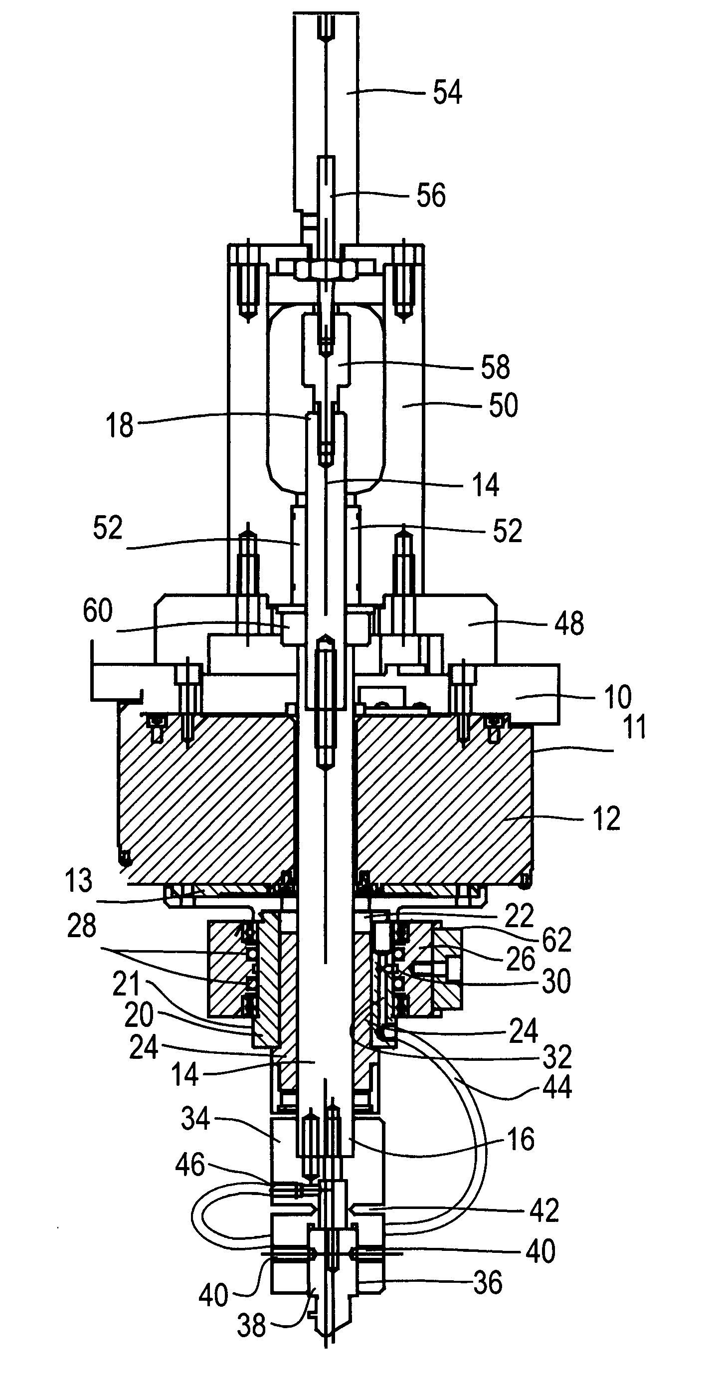
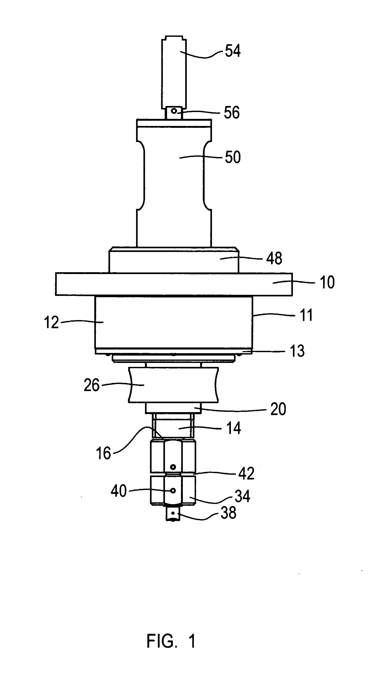
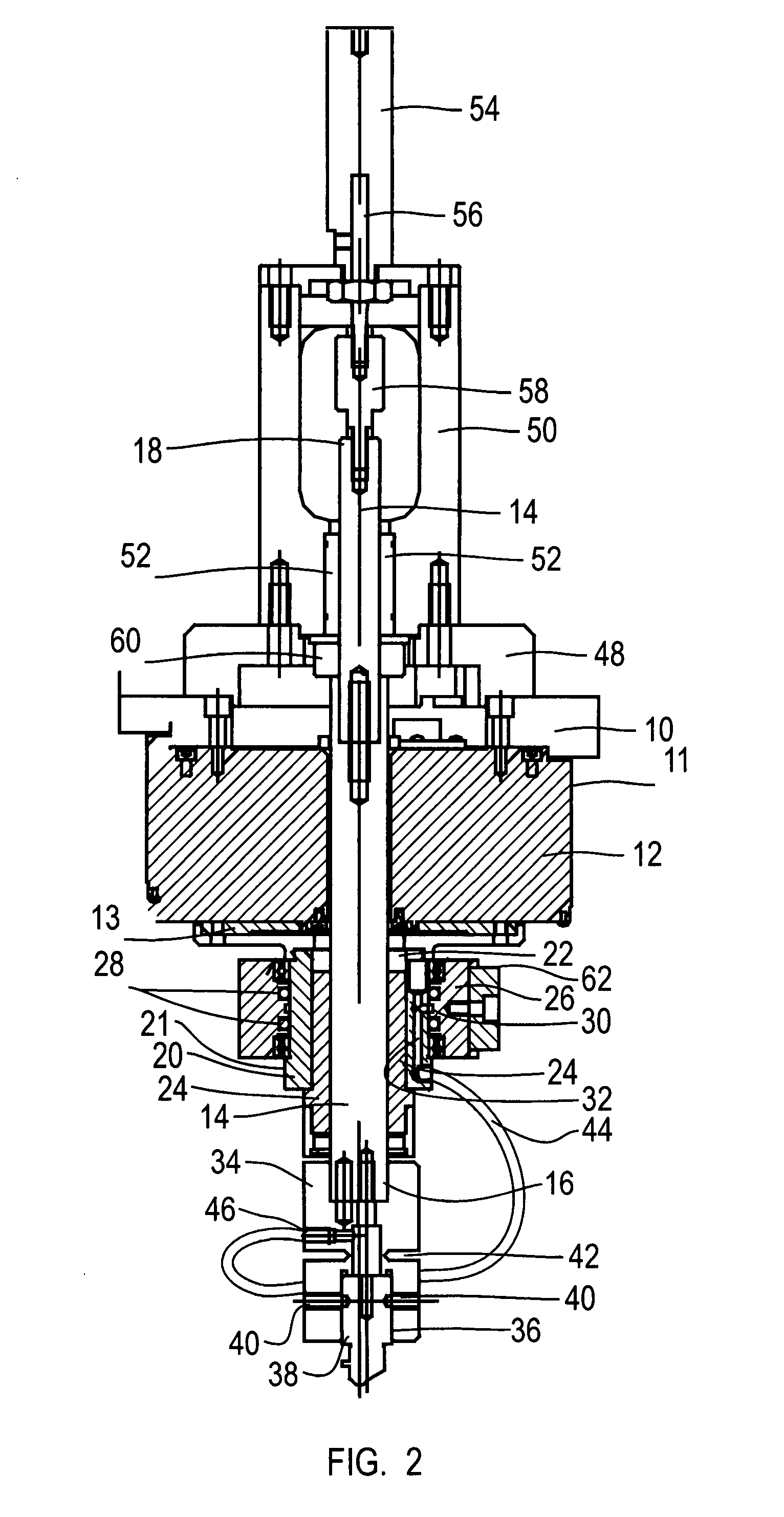
[0017]The cutting head assembly of the present invention is designed for use with an X, Y two plane cutting table. Commonly the cutting table will include a bridge riding on rails for motion in the X direction and a cutting head mount positioned on the bridge for movement in the Y direction. The cutting head mount (not shown) includes a mounting flange 10. Fixed to and directly under the mounting flange 10 is a hollow bore high torque servo motor 12. The housing 11 of the motor 12 is fixed to the flange 10. In operation, the motor 12 drives a rotating plate 13 that extends below the motor housing 11. A spline shaft 14 extends through the hollow bore of the servo motor 12 and through the flange 10. The spline shaft 14 has opposed ends 16, 18 extending below (end 16) the servo motor 12 and above (end 18) the flange 10.

[0018]A drive adaptor 20 is fixed to the rotating plate 13 of the servo motor 10. The drive adaptor 20 defines a bore 22 about its center line through which the spline ...


PUM

PropertyMeasurementUnit
circumferenceaaaaaaaaaa
flexibleaaaaaaaaaa
dimensionaaaaaaaaaa

Abstract

A cutting head assembly for use in cutting plate glass has a simplified drive train, all positioned about the vertical rotational centerline. The drive train includes a hollow bore drive motor having a drive adaptor directly engaged with a spline shaft that extends through the hollow bore. The lower end of the spline shaft is directly engaged with a cutting tool holder for retaining a cutting tool. The drive motor imparts rotational movement to the cutting tool through the spline shaft and the cylinder imparts vertical movement to the cutting tool by vertical movement of the spline shaft.

Description

BACKGROUND OF THE INVENTION[0001]The present invention provides a glass plate cutting head designed to create a cut line in a glass panel, for use in the breaking of the glass panel along the cut line to form an edge having a specified dimension and shape. Such cutting heads are commonly used in connection with two axis glass shape cutting tables wherein the cutting tool is programmed, commonly through CNC controls, to create a cut line on a flat glass panel in accordance with a preprogrammed shape and design.[0002]Currently, commercially available glass cutting heads generally fall into two categories. The first category is a non-powered floating head wherein the cutting tools mounted in bearing supports to be free floating. As the glass cutting machine is operated to move the cutting head along a pattern, the cutting tool is found to trail the direction of travel of the vertical center line of the cutting head. Since the cutting tool is free floating in its bearing support, the tr...

Claims


Application Information

Patent Timeline
Patent Type & Authority Patents(United States)
IPC IPC(8): B23C1/06B23C3/00B23Q5/04
CPCB23Q1/4804C03B33/10Y10T409/309408Y10T408/6757Y10T409/306776Y10T409/303976Y10T83/0348Y10T83/8719
Inventor GOTTSCHALK, CHARLES E.
Owner GLASSLINE
Why Eureka
Try Eureka